Continue to Site
Follow along with the video below to see how to install our site as a web app on your home screen.
Note: This feature may not be available in some browsers.
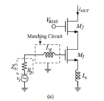
I am reading this paper and in formula (11 ) page 3, it shows that minimum noise factor Fmin isn't affected by Ls. Please look at this:
**broken link removed**
Hello,Assuming the input and output noise of the transistor are correlated, and the inductor is lossless, then I don't see how the inductor could possibly change Fmin. But it will change how Fmin is actually achieved.
Hello,Assuming the input and output noise of the transistor are correlated, and the inductor is lossless, then I don't see how the inductor could possibly change Fmin. But it will change how Fmin is actually achieved.
Why would changing the gain necessarily change Fmin?Hello,
Ls is lossless; it doesn't contribute noise source to the circuit but it changes the circuit topology and therefore changes voltage gain and finally changes Fmin. That is my thought.
Because it's a very useful metric for selecting LNA transistors.I wonder why Fmin has such a meaning? I have searched a lot but can't find that definition.
Why would changing the gain necessarily change Fmin?
May I know where to find that definition?Because it's a very useful metric for selecting LNA transistors.
Why would a change in gain necessarily change input referred noise? For example, if I take a matched LNA and measure its NF, then add an attenuator on the output and measure it again, I get the same NF, right? Of course, adding a feedback component is not the same thing, but that has nothing to do with the gain in the overall amplifier.Because when we add Ls into the circuit, the circuit is no longer a cascode but a cascode degradation. Therefore, its gain also changes. The added Ls doesn't change noise source because it is losses. As gain changes, the input-referred noise (current and voltage sources) also changes => F changes.
As far as I understand it, Fmin is always derived from source pull analysis (simulated or experimental). You sweep your source impedance and measure F over the entire smith chart, and the minimum value from that F dataset is Fmin.May I know where to find that definition?