Continue to Site

Welcome to EDAboard.com

Welcome to our site! EDAboard.com is an international Electronics Discussion Forum focused on EDA software, circuits, schematics, books, theory, papers, asic, pld, 8051, DSP, Network, RF, Analog Design, PCB, Service Manuals... and a whole lot more! To participate you need to register. Registration is free. Click here to register now.

Why does this input limit circuit not work?

Status
Not open for further replies.

blapcb

Full Member level 3
Joined
Jan 7, 2007
Messages
188
Helped
2
Reputation
4
Reaction score
0
Trophy points
1,296
Location
Planet earth (most of the time)
Activity points
2,766
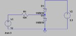
Hi. I am trying to make a circuit that will accept a voltage from 0 to 30v and limit it to 3.3v as a TTL input to my microcontroller. I am using a "classical" (i.e. often used, so I understand) design of two Schottky diodes in series (attached). In LT Spice simulation the voltage is approx 3.4v at the junction of R1/D1/D2. But in real life when I build the circuit, I get voltages all across the board all the way up to a limit of 5.7v for an input above 20v (where it seems to finally stop). Why is it not just staying at 3.4v like in the simulation? Thanks.
 

Attachments

  • InputCircuit.JPG
    InputCircuit.JPG
    11.1 KB · Views: 136

Your schematic is strange, the normal way to use a zener is like R! and D2 and the output is at the connection point between them,
why do you have D1 there?
It only adds a voltage drop of about 0.7v (diode forward voltage) .
There is also a problem because of of the high value of R1, the zener is biased with a very low current (about 1mA),
if you try to add a load it should be of high resistance (much higher that R1) or your output voltage will drop rapidly because of the voltage drop on R1.
To avoid such problems you could use a transistor connected as an emitter follower, in that type of connection the emitter will always have a voltage of about Vbase-0.6v (as long as the base current is enough to give the output current with the specified hfe)

Voltage_stabiliser_transistor.jpg

Also check something like Zener Diode Voltage Regulator - Electric Circuit for the proper calculation in zener circuits.

Alex
 

I implemented the circuit with a power supply of 7.4V and load resistance of 100K. Got an output of 3.5V (seems agreeable .. 3.3V+Schottky bias) ... what value do you get for the same inputs

Tried again with 20V .... same result .... 3.5V output
 
Last edited:

I thought you were making some kind of power supply... ignore my previous post.
You are just trying to limit a voltage to feed an input to an mcu so the current will be very small,
what i don't understand is why you are using a diode for D2 and not a zener, a 2.5 zener would be fine for this.
I haven't seen a Schottky be used this way, how is it supposed to give a lower voltage,
there is no reverse bias characteristic that resembles a zener.

Alex

---------- Post added at 11:40 ---------- Previous post was at 11:34 ----------

OK, i saw that you use a 3.3v power supply in the right side so you should get 3.3v+Vf but i still think it would be better to use a only R1 and D2 (3v zener) and get an output from there.

Alex

---------- Post added at 11:55 ---------- Previous post was at 11:40 ----------

Also note that you will have a problem with your circuit if the 3.3v is disconnected by a switch or maybe turned off (D1 cathode will be open) while the input is still connected to the 12v.
In that case you will probably damage your mcu because the input at the pin will be much more than 3.3v

Alex
 

@blapcb
I've a doubt ..... why on earth do you want to implement such a schematic ... ? ... you are varying your input from 0-30V and bringing it down to 3.3V ... whats the purpose? You are not using it for power i suppose (in which case the schematic is completely improper)?

@alexan_e -- agree with u
 

Because it is an automotive project and electrical system could be 12v or 24v (so a range is given since the voltage is not exact anyway). The signals are inputs to the MCU (like say the door being open for which you get a "high" f 12/24v).


@blapcb
I've a doubt ..... why on earth do you want to implement such a schematic ... ? ... you are varying your input from 0-30V and bringing it down to 3.3V ... whats the purpose? You are not using it for power i suppose (in which case the schematic is completely improper)?

@alexan_e -- agree with u
 

Why don't you use a circuit like this

zener-diode-voltage-regulator.gif

Use the 10k resistor, 3v zener and get the output with the 1K as you did before.
Why do you need to limit the output value of your circuit based on a second voltage (power supply)?

Alex
 

Well I tried looking in to that but the thing is that 3v zener is not exactly 3v..... they have a "range" which is based on the current (which in turn is based on the input voltage) and it can vary widely actually.


Why don't you use a circuit like this

View attachment 53880

Use the 10k resistor, 3v zener and get the output with the 1K as you did before.
Why do you need to limit the output value of your circuit based on a second voltage (power supply)?

Alex
 

@alexan_e -- schottly diodes are faster and more reliable than zeners

And what will happen if for any reason the 3.3v is not there, will the speed or reliability of Schottky protect the mcu?

Alex

---------- Post added at 13:13 ---------- Previous post was at 13:03 ----------

Well I tried looking in to that but the thing is that 3v zener is not exactly 3v..... they have a "range" which is based on the current (which in turn is based on the input voltage) and it can vary widely actually.

In a zener you have to keep the current above the minimum specification,
when you use a 10k resistor an the input is 5v then the current will me only 2v/10k=0.2ma.
You can use a lower value resistor,you can also use a TL431/TL431A
Programmable Shunt Regulator for more precision with lower bias current.

Alex
 

And what will happen if for any reason the 3.3v is not there, will the speed or reliability of Schottky protect the mcu?

Alex


hmm... missed that ....
trying to add any sort of protection will unnecessarily complicate matters... better stick to a 3V zener ... (ttl=> ~2V = logic high) should not be much of a problem.
 

And what will happen if for any reason the 3.3v is not there, will the speed or reliability of Schottky protect the mcu?
If it's "not there", then the input voltage will be limited to a lower level, isn't it?

I expect that the 3.3V is representing the logic/uP/whatsoever power supply, so the schottky diodes will limit the voltage to a diode voltage drop above it. There are various possible reasons however, why a schottky pair as well as zener diode or other voltage limiting device won't provide sufficient protection, but they have to be analysed for the actual circuit and operation conditions:

- the voltage drop of the used diode type may be too high with the respective input current. Schottky diodes are available with quite different current rating and I/V characteristic
- the supply voltage can be pulled up by the input current, additional zener diodes across the supply may be required if a sufficient minimal load to the supply isn't guaranteed
- small schottky diodes are succeptible to damage by high peak currents (e.g. ESD events), regular Si p-n diodes are possibly better suited in this case.
- very fast transients will generate considerable overvoltages with any voltage limiting device

If a precise voltage limiting for overvoltages of known maximum current is intended, schottky diodes are still my first choice
 

If it's "not there", then the input voltage will be limited to a lower level, isn't it?

You are saying that D1 cathode will be connected in any case either to gnd or to the voltage of 3.3v or any value between them,
why isn't there any possibility for the D1 to be left "floating" or connected to a high impedance source (turned off or maybe even a wire that is broken),
in that case the diode will not be able to conduct current to create the voltage drop on the resistor.

Alex
 

I didn't understand "is not there" related to a broken circuit. O.K. that's possible, but also in case of a zener diode. There are also many other possible failures that will result in fatal damage. Unless you you are not going to design security related circuits, or e.g intrinsic safe devices, you usually won't take circuit failure into consideration. If you do however, then a single zener diode won't be sufficient, you have to place at least two of them, solid axial types, not SMD devices, and also keep a lot of other restrictions.

It's appropriate to consider the electrical imperfection of protection devices, but to assume they may be broken for a standard protection level is somewhat exaggerated. In this case, the uP or logic device's substrate diodes will also handle currents up to 10 mA, by the way.
 

I tought this got posted, but can't find it.
Use the classic approach using an opto coupler.
 

Status
Not open for further replies.

Similar threads

Part and Inventory Search

Welcome to EDABoard.com

Sponsor

Back
Top