Continue to Site

Welcome to EDAboard.com

Welcome to our site! EDAboard.com is an international Electronics Discussion Forum focused on EDA software, circuits, schematics, books, theory, papers, asic, pld, 8051, DSP, Network, RF, Analog Design, PCB, Service Manuals... and a whole lot more! To participate you need to register. Registration is free. Click here to register now.

Why connect power supply ground with chassis ground through a capacitor?

Status
Not open for further replies.

swen_s

Member level 1
Member level 1
Joined
Nov 29, 2012
Messages
40
Helped
1
Reputation
2
Reaction score
1
Trophy points
1,288
Visit site
Activity points
1,598
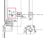
I'm wondering about the capacitor in the schematic (marked with red). Why is there a need for it?

It connects power supply ground (dangerous side) to the chassis ground (safe side). And why is there sometimes also a resistor connected across it (several mega ohms)?

I suppose the resistor discharges the capacitor after power off.

tv.png

tv2.png
 
Last edited:

I think you should search for X and Y caps. It is called Y cap.
As i know it is used to suppress EMI to obey European CE regulations.
 

I suppose the resistor discharges the capacitor after power off.
Something like this. The capacitance is too small to store enough energy to produce an electrical shock. But there's a risk that the capacitor is charged above it's voltage rating (and possibly damaged) by static electricity. The resistor drains any static electricity.
 

Status
Not open for further replies.

Similar threads

Part and Inventory Search

Welcome to EDABoard.com

Sponsor

Back
Top