Continue to Site

Welcome to EDAboard.com

Welcome to our site! EDAboard.com is an international Electronics Discussion Forum focused on EDA software, circuits, schematics, books, theory, papers, asic, pld, 8051, DSP, Network, RF, Analog Design, PCB, Service Manuals... and a whole lot more! To participate you need to register. Registration is free. Click here to register now.

Why boost converter inductor current and output capacitor current are different

Status
Not open for further replies.

Wanoz

Junior Member level 1
Joined
Apr 12, 2016
Messages
18
Helped
0
Reputation
0
Reaction score
0
Trophy points
1
Activity points
146
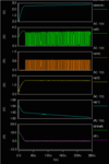
I designed a boost converter in DCM with 90nm CMOS technology. My output should be 3.5V and input is connected to a capacitor through a switch. When cap reaches 1.8V, switch is on and the converter connects to the cap. Once the cap downs to 1V, switch is off. Simulations are carried out in hspice. First current cycle of inductor and output capacitor starts really too high (e.g. 11A) other cycles is really too low (~.6A) (see attached fig. i(cload) output cap current and i(l1) inductor current legends). I don't know why huge gap between current cycles. It should start 0A and then reach max peak current, but in my design it starts 11A. Why this does not start 0A. Also, inductor current and output capacitor current should be matched when NMOS is off and current flows through PMOS or diode. Why these currents are different from each other and output cap current drops to negative value.
der11s.png

ders2.png
 

You should show a circuit diagram.

Initial current peak is probably due to abrupt turn-on of power supply, won't happen in a real application.
 

attached circuit diagram. in previous figure, inx refers to NMOS gate voltage, l2 refers to inductor voltage. C2 refers to input voltage of boost converter.
er.png
 

First current cycle of inductor and output capacitor starts really too high (e.g. 11A)
You have PMOS2 input switch. Think about a soft start circuit using it.

Why these currents are different from each other and output cap current drops to negative value.
Load current?
 

Yes, load current is different from inductor current when PMOS3 is on. What kind of start circuit can be used? Should this start circuit permanently take place in the circuit or just for simulation?
 

inductor curent waveform and output cap waveform are not the "same" in a boost converter.
Assume all the DC goes into the load, and all the AC content in the output cap.
(this assumes a resistive load)
 

Status
Not open for further replies.

Similar threads

Part and Inventory Search

Welcome to EDABoard.com

Sponsor

Back
Top