Continue to Site

Welcome to EDAboard.com

Welcome to our site! EDAboard.com is an international Electronics Discussion Forum focused on EDA software, circuits, schematics, books, theory, papers, asic, pld, 8051, DSP, Network, RF, Analog Design, PCB, Service Manuals... and a whole lot more! To participate you need to register. Registration is free. Click here to register now.

Why are we using power dividers?

Status
Not open for further replies.

alitavakol

Member level 2
Joined
Dec 1, 2005
Messages
47
Helped
2
Reputation
4
Reaction score
0
Trophy points
1,286
Location
Iran
Activity points
1,653
why we use power dividers? Is'nt it possible to simply connect three wires together?

Added after 35 seconds:

please answer.
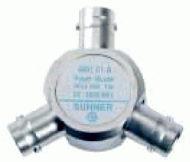
 

6db resistive power divider

Power divider achieves matched impedance at all ports at the cost of 6 dB powerloss. If you don't know why to use it, you probably don't need it and may use a T-connector as well.
 

16.7 ohm splitter circuit

alitavakol said:
why we use power dividers? Is'nt it possible to simply connect three wires together?

Added after 35 seconds:

please answer.

At RF, you need to apply transmission line theory and not traditional/simplified KVL / KCL.
 

Re: Power divider

what is the differance between tee conectors and power deviders .
 

Power divider

From what I know, Tee connector is one of power dividers.
 

Re: Power divider

The t-junction is a power divider (3 ports network) that has the following properties:
It's a lossless network.
It's reciprocal.
BUT, it can't be matched at all ports

There are another kind of power divider that uses resistors (resistive dividers, wilkinson power dividers) that:
Are reciprocal
All ports can be matched
BUT, are not lossless networks.

The above-mentioned is because the impossibility to synthesize/create 3 ports networks with the 3 properties simultaneously.
 

Re: Power divider

My first comment is that there are a number of errors above. Use the information but check carefully that you understand the part you intend to apply.

Power dividers are used to either separate or combine signals. Numerous factors need to be considered including size, cost, bandwidth, frequency of operation, match and s11, insertion loss, isolation, phase (particularly in hybrids), performance changes as the strength and phase of input signal(s) change, dispersion, power handling, etc.

The issue is deceptively simple and can get quite convoluted. Find a text on the subject and do some reading.

Three cables can simply be connected but there are potential issues of s11, s21 and isolation. It is certainly inexpensive. Usually when something is cheap it also works badly and this is the case here. Of course, we need to understand "works badly".
 

Re: Power divider

The term power divider may be ambiguous. I understand it designating a resistive power divider. A 50 ohms resistive power divider e. g. is a T-circuit with three 16.7 ohms resistors, achieving the said 6 dB attenuation. It is generally used in labs for splitting and combining signals when impedance matching is required. The components are wideband 0 - x Ghz.

The "lossless" components are usually designated power splitters, they have limited bandwith, and are bulky and expensive. They are used in specific applications, where loss matters.

97_1209706813.gif
 

Status
Not open for further replies.

Part and Inventory Search

Welcome to EDABoard.com

Sponsor

Back
Top