Continue to Site

Welcome to EDAboard.com

Welcome to our site! EDAboard.com is an international Electronics Discussion Forum focused on EDA software, circuits, schematics, books, theory, papers, asic, pld, 8051, DSP, Network, RF, Analog Design, PCB, Service Manuals... and a whole lot more! To participate you need to register. Registration is free. Click here to register now.

Why antenna has narrowband simulation, but measurement result turns wideband?

Status
Not open for further replies.

kent5566007

Newbie level 5
Joined
May 18, 2020
Messages
10
Helped
0
Reputation
0
Reaction score
0
Trophy points
1
Activity points
148
Hi everyone:

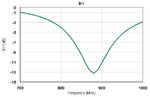
I just made a test sample for UHF antenna after simulation by HFSS 13, like following picture. Result shows narrow band with Peak freq around 865MHz.
(The impedance is not conjugate perfectly, due to some mistake during design)
2020-06-15_154134.png


But after measurement in open space, the actual result turns wide band without specified freq peak like following.
This result was measured by Voyantic software, which could measure and calculate the antenna characteristic.
Voytanic_1.jpg


The simulation setup is totally same as actual measurement, dimension, input impedance and background circumstance.
Is anyone could give a hint that why there is a such difference between real measurement and simulation?

Thanks
 

Your antenna is very narrowband according to your HFSS results, what antenna type is that?
 

Hi Volker:

It's a dipole antenna for RFID use.
 

By the way, I also put antenna dimension deviation into simulation. It also come up with almost same freq.
I try all the way to mimic the real situation, but fail.
 

If it is a regular size dipole, it must be MUCH more wideband than the HFSS result you showed (S11).

There is something wrong with your HFSS model. Or the HFSS data that you show is not S11 (reflection).
 

A Dipole Antenna cannot behave a such characteristic.There should be an error in simulation set-up.
 

Thanks for BigBoss & Volker reply.

Please let me clarify the antenna type, which is meandering dipole antenna. And I design like second picture I showing below.
According to some published research, I think the meandering dipole antenna shows s11 like what I did. Please find the pictures for your reference.
Marco Virili , Paolo Mezzanotte.png

Quote: "Design of an UHF RFID Antenna on Flexible Substrate Magnetically Coupled to the Tag"
Yassine Gmih, Abdelmajid Farchi.png

Quote: "A New Design of a Miniaturized UHF-RFID Passive Tag Antenna Based on L-Shape Radiators with Meandered Dipole"


So questions are,
1. Does meandering dipole antenna would simulate like what I did?
2. Does actual measurement would show wide band rather than "narrow peak"?
3. I also made another measurement from purchasable sample like below, and which shows wide band and no specific peak from Voytanic test kit. Does this a reasonable result?
4. If so, how should we know the peak freq of the antenna?
test sample.png


Please correct me if i am wrong and help to give a hint. Or where can I find the related research for this topic?

Thanks for your help.
 

Thanks for the calification, indeed such a miniaturized dipole isn't broadband.

Regarding the "narrow peak", you need to do the math from return loss to (S11) to power loss in transmission. 3dB return loss means 3dB mismatch loss (for transmission) and 10dB return loss means 0.46dB mismatch loss. So for transmission it is not as sensitive as the S11 peak might indicate. A "good enough" matching will be fine.

That said, your return loss at 800MHz or 1000MHz seems to be 1dB or so ... which means ~7dB loss in transmission. That should be clearly visible. But in your Voyantic diagrams, response looks rather different. To me, it is not clear what Voyantic shows here. Maybe you can discuss your findings with their support?
 
For the first antenna (UHF RFID Antenna on Flexible Substarte) I did a quick simulation with the provided dimensions, using a different EM simulator than HFSS.
For the flexible substrate I used Kapton Polyimide Er=3.45 with loss tangent 0.002.
There are many settings that can affect the return loss bandwidth in a EM simulation, but as you see, I get much wider bandwidth than you get with HFSS.
Provide more information about your HFSS setup and may find the problem.
 

Attachments

  • mean_dipole.jpg
    mean_dipole.jpg
    26.1 KB · Views: 84

Thanks for Volker's tip, I will contact them in the meanwhile.

Hi vfone,
My HFSS setting is as follpwing,
Solution type: Driven Terminal
Substrate: 0.55mm FR-4, 4.4 permitivity with 0.02 loss tangent
Trace: 1.4mil copper, 5.8e7 siemens/m
No bottom ground.
Excitation (input): resistance=21, reactance=199j
Plot reference as following,
Yassine Gmih, Abdelmajid Farchi_1.png


I just wondering, does test result should be matched between antenna resonant frequency and antenna measurement result?
Or, practically, antenna resonant frequency by simulation is just a reference?

Thanks,
 

An EM simulation for this kind of an antenna (and these frequencies) should match pretty well the measurement results.
Increase the meander trace width and you will get wider bandwidth and better correlation between simulation and measurements.
If you have access, try to use a 2D EM simulation software, because for this application will be more flexible than HFSS.
 

I just wondering, does test result should be matched between antenna resonant frequency and antenna measurement result?
Or, practically, antenna resonant frequency by simulation is just a reference?

As I tried to explain, a really bad antenna matching will have obvious effects. But there is little difference in receive signal between a "reasonable" and "perfect" antenna matching. So the usable bandwidth is larger than the narrow S11 dip indicates.

Look at the return loss vs. frequency
When antenna reflection is -3dB = 50% power, then 50% of your transmitter power is reflected, and only 50% is transmitted.
When antenna reflection is -10dB = 10% power, then 10% of your transmitter power is reflected, and 90% is transmitted.
 

My HFSS setting is as follpwing,
Solution type: Driven Terminal
Substrate: 0.55mm FR-4, 4.4 permitivity with 0.02 loss tangent
Trace: 1.4mil copper, 5.8e7 siemens/m
No bottom ground.
Excitation (input): resistance=21, reactance=199j

What is your HFSS terminal impedance set to? The 21 + j199 you specified here? Do you have a matching network? How are you actually exiting this antenna in measurement?

In real life, your VNA probably has a port impedance of 50 Ohms, which of course would provide a different result than a simulation with 21 + j199 Ohms.
 

Status
Not open for further replies.

Part and Inventory Search

Welcome to EDABoard.com

Sponsor

Back
Top