Continue to Site

Welcome to EDAboard.com

Welcome to our site! EDAboard.com is an international Electronics Discussion Forum focused on EDA software, circuits, schematics, books, theory, papers, asic, pld, 8051, DSP, Network, RF, Analog Design, PCB, Service Manuals... and a whole lot more! To participate you need to register. Registration is free. Click here to register now.

Whirlpool washing machine l1961

Status
Not open for further replies.

vivedin

Newbie
Joined
Apr 9, 2021
Messages
1
Helped
0
Reputation
0
Reaction score
0
Trophy points
1
Activity points
14
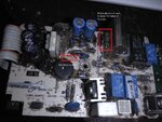
Help Needed for Whirlpool Washing Machine SMPS board. Machine dead found two resistors burnt R20 and R21. R20 is 1/4W resistance completely burnt out. R21 appears to be 1W burnt. Not sure about the IC LNK304 and other parts.

What is the value for R20 ?

Need the schematic diagram or any help with the resistance values. Also suggestion what else parts might have gone bad. IC LNK304 appears ok physically as it was replace earlier. I have attached the image of the board its for L1961 Quartz Drive PP6 Washing machine model is D650 Top load automatic.

Waiting for replies from experts.

Regards
 

Attachments

  • R20-21 (1).jpg
    R20-21 (1).jpg
    281.9 KB · Views: 159

The cylindrical resistor has bands colored brown, black, and a burned discolored band. From the size its rating looks like 2 Watts.
I guess 1 or 10 or 100 ohms.
(And maybe a black band at the other end designating tolerance?)

The obvious burnt components may have gone bad because of another component going bad. Can you locate a path which overmuch current might have taken? This might include anything: control devices, copper traces on the board.

Does the motor smell burnt? If so then its operating characteristics might have changed. It could be the cause of burnt parts, and there may be no use in trying to repair those parts.
 

At the top side of the picture, we can see what seems a large 3-pins connector, perhaps the Line, Neutral and Eart power bus; also, on the nearby, two rectfier big diodes and two bulk capacitors lead to the assumption from the components disposal that R21 could be part of the 1st stge switched power supply, more exactly the Resistor/Capacitor/Diode rectificaction. There is a thread on Edaboard where someone give some answer that somehow corroborates above @BradtheRad's reply: 100R


As per R20, since it is too close from other parts of this stage, I wiould bet it should not be difficult to infer its role, have a look on the solder side of the PCB and make a sketch of the above resistor surrounding circuitry. If you have look, the failure would be due to some overvoltage on the mains grid when equipment where not opperating, therefore restricting the damage to this electronic input stage only.
 

Status
Not open for further replies.

Part and Inventory Search

Welcome to EDABoard.com

Sponsor

Back
Top