Continue to Site

Welcome to EDAboard.com

Welcome to our site! EDAboard.com is an international Electronics Discussion Forum focused on EDA software, circuits, schematics, books, theory, papers, asic, pld, 8051, DSP, Network, RF, Analog Design, PCB, Service Manuals... and a whole lot more! To participate you need to register. Registration is free. Click here to register now.

Which one is ferrit rod for am radio

Status
Not open for further replies.

Errick27

Newbie
Joined
Sep 26, 2020
Messages
3
Helped
0
Reputation
0
Reaction score
0
Trophy points
1
Activity points
26
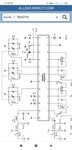
Hi,2 years ago i found an old radio from my grandma house,its 2 band fm am that using tea5710 and lm386,im just a amateur back then,i tried to fix the fm section,and im not caring about the am,but now i want to fix the am section,i almost done everything,just need an ferrite rod for the antenna,the rod was gone,now i have a rod from another radio,but ir have different pin,my radio havent rod pin,i already look at the datasheet but cant figure out which one is the ferrite rod. Can you plz help me.
Thanks
3328.jpg
3356.jpg
3356.jpg
 

Attachments

  • Screenshot_2020-09-26-14-18-09-264_com.kiwibrowser.browser.jpg
    Screenshot_2020-09-26-14-18-09-264_com.kiwibrowser.browser.jpg
    279.3 KB · Views: 55

If the radio has a ferrite rod, you have to refer to the schematic with tuned AF frontend on next datasheet page. L1 can be implemented as ferrite rod.

1601106744734.png

--- Updated ---

It's well explained in the application circuit layout and BOM.
 
If the radio has a ferrite rod, you have to refer to the schematic with tuned AF frontend on next datasheet page. L1 can be implemented as ferrite rod.

View attachment 164351
So thats L1 as primary coil,and for the secondary?,L2 is used for fm(from the datasheet)
If the radio has a ferrite rod, you have to refer to the schematic with tuned AF frontend on next datasheet page. L1 can be implemented as ferrite rod.

View attachment 164351
--- Updated ---

It's well explained in the application circuit layout and BOM.
So that L1 is the primary,and L4 is the secondary?,then both were connected to a different variable caps,i cant find the varicap at my board,it just 2 variable condesator,that used for tuning am and fm band
 

L1 and L4 are different inductors. L1 is the ferrite cored coil, L4 will be a screened coil used in the local oscillator. The dotted line indicates there should be four capacitors ganged together. Two used for the AM circuit and two for the FM circuit. It is necessary for L1 and L4 to be tuned simultaneously (although at different frequencies) for the device to work so they must both be present in the tuning capacitor body.

Brian.
So that L1 just use 1 coil ferrite?
 

Status
Not open for further replies.

Part and Inventory Search

Welcome to EDABoard.com

Sponsor

Back
Top