Continue to Site

Welcome to EDAboard.com

Welcome to our site! EDAboard.com is an international Electronics Discussion Forum focused on EDA software, circuits, schematics, books, theory, papers, asic, pld, 8051, DSP, Network, RF, Analog Design, PCB, Service Manuals... and a whole lot more! To participate you need to register. Registration is free. Click here to register now.

Which is the best way to do a Current Sense Transformer for a Full Bridge SMPS?

Status
Not open for further replies.
Z

zenerbjt

Guest
Hi,
Please advise which is the best position/configuration for a primary side current sense transformer for a Full Bridge SMPS? (Comparative Schems are as attached).

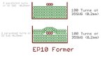
Also, the 100:1 Current sense transformer that will be used is shown in cross section….but two different winding configurations. Please advise which is the best winding configuration? (one is sandwiched and one isn’t)
 

Attachments

  • Schem _FullBridges with CSTs.pdf
    193.4 KB · Views: 109
  • EP10 CST.jpg
    EP10 CST.jpg
    90.2 KB · Views: 80

When I picture where the lines of flux are strongest, and where the wires interact most closely, I believe the sandwiched winding scheme creates better coupling. I can't prove it with a formula. Just my educated guess.
 
  • Like
Reactions: zenerbjt

    Z

    Points: 2
    Helpful Answer Positive Rating
Hi,

Best... what means "best".
Low cost, smallest, lowest capacitive coupling, best pri sec coupling, lowest series inductance....

Klaus
 
  • Like
Reactions: zenerbjt

    Z

    Points: 2
    Helpful Answer Positive Rating
Thanks, i mean best pri-sec coupling.....we can reduce the capacitance of the sandwiched one by using TIW for the primary.
I believe that the non-sandwiched one would suffer very poor coupling because its just one turn on top of 100 turns, and it is only in a single place, and not even covering the whole layer. Woudld you agree?
 

Status
Not open for further replies.

Similar threads

Part and Inventory Search

Welcome to EDABoard.com

Sponsor

Back
Top