ntr97
Newbie level 3
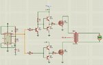
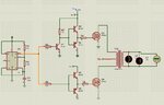
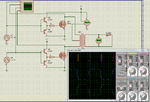
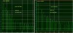
How to fix voltage drops at 220V in this inverter Circuit
How can i fix the voltage at 220V , when I connect the voltmetre with no load it shows 220V but when I add a lamp it drops to 87V
What can I do to improve the circuit and what are your opinions about it
Help please !
How can i fix the voltage at 220V , when I connect the voltmetre with no load it shows 220V but when I add a lamp it drops to 87V
What can I do to improve the circuit and what are your opinions about it
Help please !