Continue to Site

Welcome to EDAboard.com

Welcome to our site! EDAboard.com is an international Electronics Discussion Forum focused on EDA software, circuits, schematics, books, theory, papers, asic, pld, 8051, DSP, Network, RF, Analog Design, PCB, Service Manuals... and a whole lot more! To participate you need to register. Registration is free. Click here to register now.

What's the function of this part in a RF power transistor ?

Status
Not open for further replies.

Boowei

Member level 1
Joined
Dec 20, 2006
Messages
37
Helped
0
Reputation
0
Reaction score
0
Trophy points
1,286
Location
China
Activity points
1,522
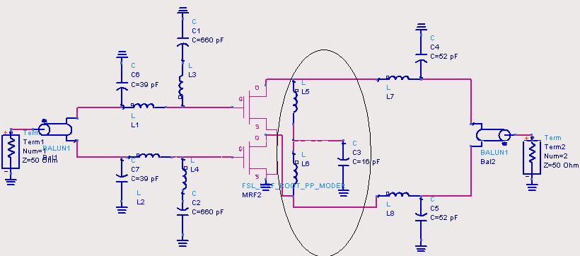
Who can tell me what's the function of this part (L5,L6 and C3)in a RF power transistor ?
the transistor operation frequency:470MHz-860MHz
Pout=180W
the inductance value of L5 and L6 is very small about <1nH.
Thanks.
 

Re: What's the function of this part in a RF power transisto

They form a 2nd harmonic trap to improve intermods.
 

    Boowei

    Points: 2
    Helpful Answer Positive Rating
Re: What's the function of this part in a RF power transisto

Hi

for differential mode, the node where two inductors are connected together is on GND, capacitor is not seen. Basically it is an inductor to GND. So, the second harmonic will see higher impedance of the inductor to GND then the fundamental, looks like it will not prevent 2nd harmonic presence at the output.

On the contrary, for common mode the node where two inductors are connected together is open, so both inductors are connected in parallel and then in series with the capacitor.

Looks rather like common mode trap to me, although vfone could be wright, this kind of circuit is in some applications required to work for second harmonic, not always as a trap, sometimes as impedance control for harmonic termination, you will need to check the values.

flyhigh
 

    Boowei

    Points: 2
    Helpful Answer Positive Rating
As vfone and flyhigh have said this structure could act as a filter for unwanted tones in the output spectrum, depending on the inductance value. Also this would provide the connection point for dc bias to the drain of each device. This schematic is set-up for linear analysis (at 180W!!) so a bias voltage source are not required, however, if this circuit was reconfigured for Harmonic Balance analysis then this source would be necessary, provided a suitable model for the transistors was also included.
 

    Boowei

    Points: 2
    Helpful Answer Positive Rating
Re: What's the function of this part in a RF power transisto

Thank vfone,flyhigh,RealAEL.
Who can tell me more detail about it in theroy,or some paper or book about it.
 

Re: What's the function of this part in a RF power transisto

this is most likely a way to feed the B+ to the transistors via the shunt capacitor.
 

Re: What's the function of this part in a RF power transisto

flatulent
what is B+?
 

The power supply, or have do you have an idea, how the amplifier can operate without a supply. The questioned LC filter is most likely nothing but a supply bypass. The only point, the contradict it, is the 15 pF value. I would think different about it, if the supply is explicitely shown in the circuit.
 

Re: What's the function of this part in a RF power transisto

Even if that point is a DC bias (there will be a series choke from that point), still it is a 2nd harmonic trap. I use this very often to improve with few dB’s the intermods.
 

    Boowei

    Points: 2
    Helpful Answer Positive Rating
Re: What's the function of this part in a RF power transisto

Thank all.
I think vfone is right.However can you explain how the LC trap the 2nd harmonic and improve the intermods?
 

Re: What's the function of this part in a RF power transisto

There are hundreds of articles and books regarding this issue, but probably the best written is RF Circuit Design of C. Bowick.
I am attaching from the book the files that you are interested.
 

    Boowei

    Points: 2
    Helpful Answer Positive Rating
Re: What's the function of this part in a RF power transisto

Thank vfone.
 

I guess it is part of matching circuit.
To prove that it is not part of matching and just to suppress the intermods, you can remove these parts and simulate for basic needs.
 

Re: What's the function of this part in a RF power transisto

Yeah…usually knowledge is better than guessing…
 

Can you tell me this is an permathced transistor or not? I'm thinking that, it's a unmarthed device. So to reach wide band matching, you need a L-shunt section. Always we do this inside the package. Hope it helps.

Added after 1 minutes:

One thing: The less value of the inductor, the easier the mathing is!
 

    Boowei

    Points: 2
    Helpful Answer Positive Rating
Re: What's the function of this part in a RF power transisto

Hi chaoFan
the L-C is inside the package.But I have on idea of how the L-c match the device.
Have some book or paper about it?
Thanks.
 

Hi,Boowei,
It's inside package? So it makes sence. Let me explain roughly, If you look into the die, you will see an impedance like A-jB, most time it's less then 1ohm, it's not easy to use. Then you might want a L-shunt matching section first, so the A part of the impedance goes higher but the B part dereases. That means the Matching Q getting lower, if you try this in smith chart, you'll see the less value of the inductor,the lower tht Q is, then after, we always connect a serie L, so the impedance at the device level is like C+jD. So the impedance is more friendly and higher to use.
Hope it helps!

Thanks!

Chanfan
 

Re: What's the function of this part in a RF power transisto

Hi chaoFan
Can you give me some directly help with email?my email is liok802000@yahoo.com.cn
Thank.

Added after 50 seconds:

Hi chaoFan
Can you give me some directly help with email?my email is liok802000@yahoo.com.cn
Thank.
 

Re: What's the function of this part in a RF power transisto

Hi chaoFan
As you say shunt L can lower the Q.but what is the function of C3.
 

Status
Not open for further replies.

Part and Inventory Search

Welcome to EDABoard.com

Sponsor

Back
Top