Continue to Site

Welcome to EDAboard.com

Welcome to our site! EDAboard.com is an international Electronics Discussion Forum focused on EDA software, circuits, schematics, books, theory, papers, asic, pld, 8051, DSP, Network, RF, Analog Design, PCB, Service Manuals... and a whole lot more! To participate you need to register. Registration is free. Click here to register now.

What should be Vref in CMFB?

Status
Not open for further replies.

circuitking

Full Member level 5
Joined
Jan 8, 2018
Messages
291
Helped
1
Reputation
2
Reaction score
1
Trophy points
18
Activity points
2,503
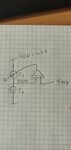
Hello, the setup in the attachment will make sure that I1 will become equal to I2. But does this process depend on what is the value of Vref? how to choose this value? How choosing one value of Vref impacts the process of making I1 = I2 than choosing some other value for Vref.
 

Attachments

  • WhatsApp Image 2021-02-26 at 1.51.48 PM.jpeg
    WhatsApp Image 2021-02-26 at 1.51.48 PM.jpeg
    71.3 KB · Views: 94

Hello,
VREF should ensure that I1=I2 so there is no transistor is pulled out of saturation and consequently to either ground or VDD rails.
A typical value is (VDD-VSS)/2 but it is not restricted to this value. Just ensure all transistors are in saturation for this value.
 

Hello,
A typical value is (VDD-VSS)/2 but it is not restricted to this value. Just ensure all transistors are in saturation for this value.

Thanks, so it can be any value that makes sure all transistors are in saturation.

Hello,
VREF should ensure that I1=I2 so there is no transistor is pulled out of saturation and consequently to either ground or VDD rails.

But in LVDS the switching transistors are not necessarily need to be in saturation right, then what is the point of having CMFB in that case?
 

I do not know about LVDS. I was talking about fully differential OTA.
 

Vref should be equal to the intended common mode voltage, e.g. 1.2 V for LVDS drivers.
 

Simply put, the CMFB controls I1 such that Vocm=Vref. That means that I1 is slightly so different (practically identical) compared to I2. The difference goes into the equivalent output resistance at the middle node to provide the above equality. Obviously, if the output stage is just modeled with ideal current sources, the voltage at the middle can be anything.
 
Well, if you have two ideal current sources connected in series, and you are controlling the current through one of them, then you have an infinite gain amplifier. Throw in the output transconductance of the current sources, and you have a finite gain and then it should be fine.
 

Status
Not open for further replies.

Part and Inventory Search

Welcome to EDABoard.com

Sponsor

Back
Top