Continue to Site

Welcome to EDAboard.com

Welcome to our site! EDAboard.com is an international Electronics Discussion Forum focused on EDA software, circuits, schematics, books, theory, papers, asic, pld, 8051, DSP, Network, RF, Analog Design, PCB, Service Manuals... and a whole lot more! To participate you need to register. Registration is free. Click here to register now.

What should be a simple High side Mosfet switch is Killing Mosfets

Status
Not open for further replies.

Pat-UK

Newbie level 4
Joined
Feb 20, 2006
Messages
7
Helped
0
Reputation
0
Reaction score
0
Trophy points
1,281
Activity points
1,343
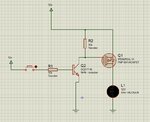
mosfet001.jpg

I have searched and cant seem to find the solution,

This design has always worked fine for low power outputs, but this seems to be destroying Mosfets on higher loads

I am using it to light a 55w halogen, if you turn it off and on slowly, then this is fine, but flash it a few times and the Mosfet goes short and starts cooking itself.

Unfortunatly as this is in a vehicle, it has to be Highside and has to be switched with a high signal, so am using P channel 50a Mosfets IPD50P04L **broken link removed** gate held high with 10k resistor, I am using a NPN transistor to switch the Mosfet on.

I know its a simple circuit, but cant seem to see why the halogen lamps keep making the magic smoke out of the Mosfets any help or add ons would be great.

Thanks
 

If you have long load cables, the energy stored in the load circuit could exceed the avalanche rating. More likely you get overvoltage at the source node due to ringing input voltage which exceeds the Vgs maximum rating. TVS diodes can be used to cut possible overvoltage.
 

Many thanks for the quick reply, there is almost NO distance between the MOSFET and the bulb, it's a wide PCB track and then a contact which the bulb plugs into so no capacitance in the cable on the load side, however the switch side cabling does go round the houses. So there could lie the problem
 

Along the lines of what FvM said, I would put 10v zener from gate to source of fet...as you know Cathode to Source.

Add a 510r or so resistor between bjt collector and fet gate.
Add a diode across the bulb, anode to ground

Basically I am just trying thinking about the problem of breaking the inductive current of any stray inductances of the cabling etc, or of the bulb.

Is there a huge surge current through a halogen bulb at the pojnt of turn on?..if so , add say an ntc or a series power resistor.
And yes, as per FvM, a TVS say 30v, across the fet drain to source, make it bidirectional one if poss, otherwise cathode to 12v
 
Last edited by a moderator:

Thank you very much :)

Will add that and report back :)
 

Hi,

Either current and power dissipation causes heat that destroys the fet, or overvoltage.
With over voltage I expect no heat at first. But th high voltage may kill isolation inside the fet, this causes leakage current, evenue when the fet us switched off. Further destroying of the isolation kills the fet totally.

*****

Input side: I'd add a ceramic capacitor next to source and gnd.
And a schottky diode parallel to the load, but near the fet. The diode rating of 1A should be sufficient.

Klaus
 

what about also putting an RC series across the +12V to ground, so as to quench any inductive ringing of the supply cables coming to the fet/bulb....make it a 1R and say a 10uF or something...you get the idea, the cap will "short" the ring to the resistor, and dissipate the bounciness there....but because of cap, it dissipate nothing when in normal running
 

Brilliant, all great info, will have a look at it again in the morning and see where we end up.

Would be great to get to the bottom of it, just frustrates me that if its just urned on and off slowly, not a problem, absolutely no heat and will run for hours doing this. But flick it on and off quickly a couple of times and poooooof game over.
 

Had some time this morning to have another look at this and thanks to the advice think I'm pretty much there.

What I had discovered was that if this was tested on the bench Power supply the short "turn on" leads it worked fine, it was only when it was tested in a vehicle that it started killing fets.

The 12v supply was fine with short cable runs, however the turn on wires in the car went round the houses, and were most likely the cause of the issues so with this in mind I went with the 10v Zener across fet and used 480ohm from NPN to gate. And put small ceramic caps to GND

Been on test for a little while today and seems to be OK, but am going to give it a proper run for its money tomorrow, once I have it nailed down to the point it's reliable, I will then be looking to implement more protection as advised to ensure longevity.

Many thanks
 

I'm hoping so, so far so good, but I'll know for certain tomorrow, I'm going to have it running all day flashing as and when I get a chance to be near it, I was planning on using a dirty old relay controlled by a pic and n Chanel mosfet to test it all day, but that'll be over kill, in real terms it'll only ever get flashed a dozen times. But just need to be sure it'll be OK
 

Status
Not open for further replies.

Part and Inventory Search

Welcome to EDABoard.com

Sponsor

Back
Top