antonydublin
Newbie level 5
Hello, guys.
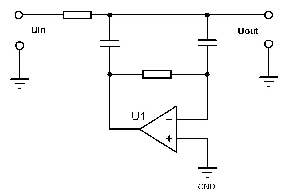
What kind of filter is that?
I could not find information on it, its properties and the calculations.
Where it can be read?
Thanks.
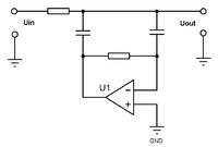
What kind of filter is that?
I could not find information on it, its properties and the calculations.
Where it can be read?
Thanks.