Welcome to our site! EDAboard.com is an international Electronics Discussion Forum focused on EDA software, circuits, schematics, books, theory, papers, asic, pld, 8051, DSP, Network, RF, Analog Design, PCB, Service Manuals... and a whole lot more! To participate you need to register. Registration is free. Click here to register now.
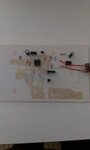
Without checking the correct connections - I think you have terribly bad solder connections, and a possible short circuit, s. the marked area.
With an Ohm meter, check for possible short circuit, and the passage of your solder connections.
Hello erikl
Thanks again for reply.After checking pcb i find following
1)No short circuit is detected
2)Every solder joint is connected with other
joint with which it should be connected
+Removed the capacitor but did not make any difference
+checked +ive and -ive voltages w.r.t ground which are correct
+ d.c voltage amplify when apply non inverting pin of op amp
Horrible PCB - you should look into good RF layout techniques.
What is the red wire linking the ends of the potentiometer? Looks like you shorted it out instead of using the center pin.
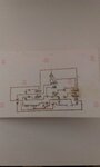
What is the first IC type? You have it configured to drive into a 10 Ohm load when the potentiometer is set to zero resistance and a gain of ~1000 when at maximum resistance, both very unlikely to work.
I shorted the central pin to one of its side pin to get variable resistance.
but It is in fact giving variable resistance as measured by multimeter.
My intention was to get maximum gain of 100 in case of very low signal.
what do you advise to do?
Thanks
Sorry feedback variable resistance in circuit is of 1 K.
This site uses cookies to help personalise content, tailor your experience and to keep you logged in if you register.
By continuing to use this site, you are consenting to our use of cookies.