Continue to Site

Welcome to EDAboard.com

Welcome to our site! EDAboard.com is an international Electronics Discussion Forum focused on EDA software, circuits, schematics, books, theory, papers, asic, pld, 8051, DSP, Network, RF, Analog Design, PCB, Service Manuals... and a whole lot more! To participate you need to register. Registration is free. Click here to register now.

What is wrong with this circuit?

Status
Not open for further replies.

gary36

Full Member level 4
Joined
Mar 31, 2018
Messages
208
Helped
0
Reputation
0
Reaction score
0
Trophy points
16
Activity points
1,806
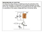
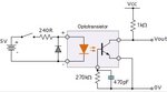
I have simple relay driver shown in the figure below. 24V and 5V are isolated. Relay coil current is around 24mA. When I power on, relay chatters heavily even through IN is connected to ground. What could be the problem?. I simulated this circuit and it worked fine.
Circuit.png
 

could be the problem?
Start debugging the circuit point to point, checking measured value against expected value. Since it implements a cut/saturation logic, it is easy to confirm if some node is close to Vcc or GND, as you switch Vin from 5v to 0v. BTW, is U1 really necessary ? I would inject the signal accross R1 directly on the pin U2:1.
 
Hi,

What's the relay model? Please post a link to its datasheet.
 

how do you know the relay current is 24 mA?
the coil is connected to the 24 V supply and through the transistor to ground
there is no current limit, so the coil resistance, which is not likley 1000 ohms, is the only current limit
what is the part number of the relay?
 

Hi,

Unlikely but maybe when NSS60201 is turned on, lack of current limiting makes 24V dip below coil 'hold' voltage so it turns on then off, then as 24V returns to nominal level with coil de-energized, it turns on again until supply drops again and so on.
--- Updated ---

Also, what about moving R3 pull-down after R2, so it's next to the base?
 
Last edited:
I would think that R3 is not necessary and can be removed entirely from the circuit.
 

Do you have large ripple on the 24V power supply or AC voltage between both grounds?
 

R3 is required to absorb leakage to prevent Q1 from turning on when opto is off.

Leave R3 where its at, otherwise its a V divider. Less drive for Q1. Although I would have
to sim that to confirm.


Regards, Dana.
 

Yeah, it is the strange behavior. any other insights. Relay coil resistance is around 1k, measured resistance across the coil.
 

you may have to put 100uf/35v or 50v capacitor across the IN4148 diode with +ve at the +24vdc side and -ve at
the transistor collector/diode anode side. it will solve the problem.
 

Attachments

  • reduce relay chater.JPG
    reduce relay chater.JPG
    34.1 KB · Views: 194

R3 is required to absorb leakage to prevent Q1 from turning on when opto is off.
...
Oh yes. I didn't see that. Good point.

--- Updated ---

Yeah, it is the strange behavior. any other insights. Relay coil resistance is around 1k, measured resistance across the coil.
Okay.

What about some detail about the 24V supply? Where are you getting it from? Hope you're not overloading it. Please brief us on your 24V supply.
--- Updated ---

Also, is the relay coil suitable for 24V operation? Why not provide a link to the datasheet?
 
Last edited:

part number of relay is not legible. btw same relay was used in other applications and it works fine. So relay is not an issue. I do not quite understand why relay should chatter, when input is driven low?
 

I do not quite understand why relay should chatter, when input is driven low?
Possible reasons have been already mentioned. Generally, it's possible due to high opto coupler current gain and noise superimposed to the power supply or opto common mode voltage. Optimal solution would be a RC filter and relays driver with hysteresis.
 
...
I do not quite understand why relay should chatter, when input is driven low?
With this I guess you're referring to contact bounce which is a normal thing for electromechanical relays and occur as a result of the impact of their collision and is more of a transient response, and dies out with time. This is often taken care of by connecting an RC snubber across the contacts just like FvM mentioned.

Contact chattering goes beyond contact bouncing though. They usually are caused majorly by coil voltages dipping below the holding voltage, just like d123 mentioned and they occur continuously even during 'normal operation'. Overloading could cause voltages to dip when overload protection is triggered.
 

Observation. When IN is connected to gnd, relay chatters. When IN is connected to 5V, relay gets properly energized and switches ON.
 

Observation. When IN is connected to gnd, relay chatters. When IN is connected to 5V, relay gets properly energized and switches ON.
The situation is much clearer now.

The datasheet for the buffer 74LVC1G34 states that it has a low level output current can can be up to 32mA at Vcc of up to 4.5V. That should be the first suspect. I suggest that you take away that buffer from the circuit. I would suggest that you break the connection at U1:Y terminal to check whether the chattering will stop.

BTW, where is IN signal coming from? Can't the signal be used to drive U2 LED directly through the series resistor?

The 4n35 opto Iceo seems to be negligible in this case, so I wouldn't bother about the opto just yet.

OFF-POINT OBSERVATION:
For reliability sake, even when the circuit works properly, I would suggest you reduce the LED current to maybe 5mA or even lower to improve on your present CTR degradation.
 
I suppose none of the suggested modifications is addressing possible chatter causes.

I previously mentioned possible causes, unfortunately the related questions haven't been answerved yet.
 

Hi,

Generally 5V supply as well as 24V supply need a bulk capacitor and decoupling capacitor.
But I assume there is another error. Bad solder joint, wrong or defective device....

Klaus
 
Connect to ground a 270k resistor from the pin 6 of 4N35 (base of the transistor, as in the picture attached) and it will work.
The resistor may need some adjustment.
 

Attachments

  • opto.jpg
    opto.jpg
    13.9 KB · Views: 142
i think you remove the 20k resistor from the base of the transistor & put a 47uf electrolytic capacitor
at the base of the transistor. replace 4.7k with 2.2k & place a 100uf electrolyte across relay. i believe that it
will solve your problem.
 

Status
Not open for further replies.

Part and Inventory Search

Welcome to EDABoard.com

Sponsor

Back
Top