Continue to Site

Welcome to EDAboard.com

Welcome to our site! EDAboard.com is an international Electronics Discussion Forum focused on EDA software, circuits, schematics, books, theory, papers, asic, pld, 8051, DSP, Network, RF, Analog Design, PCB, Service Manuals... and a whole lot more! To participate you need to register. Registration is free. Click here to register now.

What is this transformer configuration?

Status
Not open for further replies.

LJJJ

Newbie level 3
Joined
May 10, 2010
Messages
3
Helped
0
Reputation
0
Reaction score
0
Trophy points
1,281
Activity points
1,302
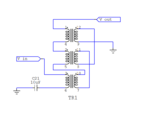
I came across this transformer circuit and wondering what is this transformer configuration called.

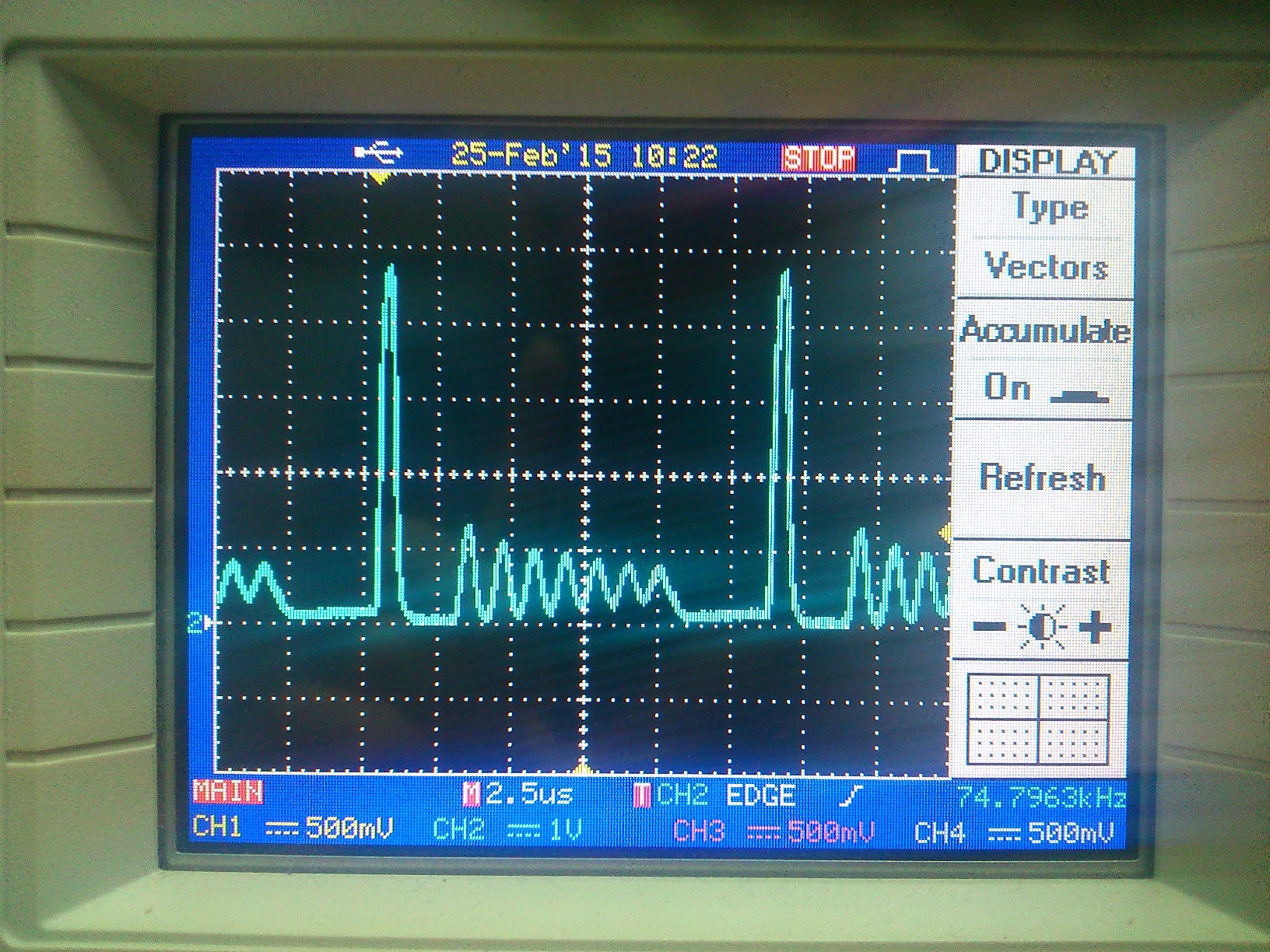
The input voltage is 1us pulse of 45V, pulse repetition frequency is 75kHz.

The output voltage after passing through a diode is 300Vdc.

I am wondering how does it step up the voltage? And what is the step-up factor?

The transformer used is as below, with turns ratio of 1:1:1:1:1:1

https://katalog.we-online.de/pbs/datasheet/749196211.pdf
 

Attachments

  • We-flex.PNG
    We-flex.PNG
    12.3 KB · Views: 125

Unusual configuration but one winding is driven, the other 5 are in series and phase so I guess it's just a 1:5 step-up configuration.

Brian.
 

Thanks. I also think so.
 

Yes, Brad the Rad is correct the transformer connected is a 75KHz pulse 45V driven single turn with a 5 parallel secondary. Where did you get the circuitry from? Interesting how you get 300V from a 45V signal running at 75KHz at around 7% duty cycle.
 

Yes sorry series, and i was on two forums at once i meant you betwixt not brad the rad.
 

I am also wondering how does it able to generate 300V dc from the pulse.

This is the pulse I measure with a 1:10 voltage divider, the pulse should be 50V to be exact, and there are some small pulses following the big pulse. When measuring with a multimeter, the input rms voltage is 5V.


Your multimeter is almost certainly calibrated for a sine wave RMS reading. With other waveforms, especially pulses it will give a false reading.
The peak voltage is from the collapse of the current as the pulse ends and depends largely on how sharp the pulse edges are and how long the pulse lasts.
Those little pulses are almost certainly resonant effects, they indicate oscillation as some of the energy is re-absorbed and released again from the capacitor and driving circuit.

Brian.
 

Status
Not open for further replies.

Similar threads

Part and Inventory Search

Welcome to EDABoard.com

Sponsor

Back
Top