Continue to Site
Follow along with the video below to see how to install our site as a web app on your home screen.
Note: This feature may not be available in some browsers.
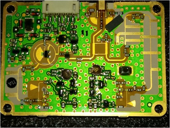


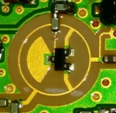
Left of first picture Is this some sort of matching network with short stubs or this is something else.
it seems that there is only one mixer here. Rat-race with diode pair.and Is the 90 hybrid is used for another mixer in this board?