Welcome to our site! EDAboard.com is an international Electronics Discussion Forum focused on EDA software, circuits, schematics, books, theory, papers, asic, pld, 8051, DSP, Network, RF, Analog Design, PCB, Service Manuals... and a whole lot more! To participate you need to register. Registration is free. Click here to register now.
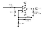
If we look at the circuit as three different parts, things might look a little different. Looking at the output of the circuit i would say that the zener diode and the 100Ohm resistor constitute a current and voltage limitation. The negative input terminal is preceeded by a passive high pass filter; and the positive feedback has the behavior of a gain controlled integrator. Putting these three units together, I would say that this circuit is a voltage limited gain controlled bandpass filter, through which the gain of the pass band can be set via the feeback resistor and the grounded resistor of the positive input terminal. The cutoff frequencies are determined by the respective capacitances and RC constants. The maximum output voltage is set by the zener diode; and finally the 100Ohm output resistor could be used as a current limiter of some sort.
I don't think it is a bandpass filter. The feedback is positive, not negative so the gain will be the open loop gain of the opamp. It is a very bad circuit, whatever it is trying to do. The opamp will try to drive quite a lot of current in to the zener - there is no limiting resistor.
I thought about that too, and accordingly i think that the output resistor is meant to be placed before the zener to limit the current going through it. I also think the zener diode is placed there to limit the output because of the positive feedback; ie so that the output isn't clamped by the rails.
This site uses cookies to help personalise content, tailor your experience and to keep you logged in if you register.
By continuing to use this site, you are consenting to our use of cookies.