Continue to Site

Welcome to EDAboard.com

Welcome to our site! EDAboard.com is an international Electronics Discussion Forum focused on EDA software, circuits, schematics, books, theory, papers, asic, pld, 8051, DSP, Network, RF, Analog Design, PCB, Service Manuals... and a whole lot more! To participate you need to register. Registration is free. Click here to register now.

What is the transfer function of this bandpass circuit?

Status
Not open for further replies.

iVenky

Advanced Member level 2
Joined
Jul 11, 2011
Messages
584
Helped
37
Reputation
76
Reaction score
35
Trophy points
1,318
Location
College Station, Texas
Activity points
6,124
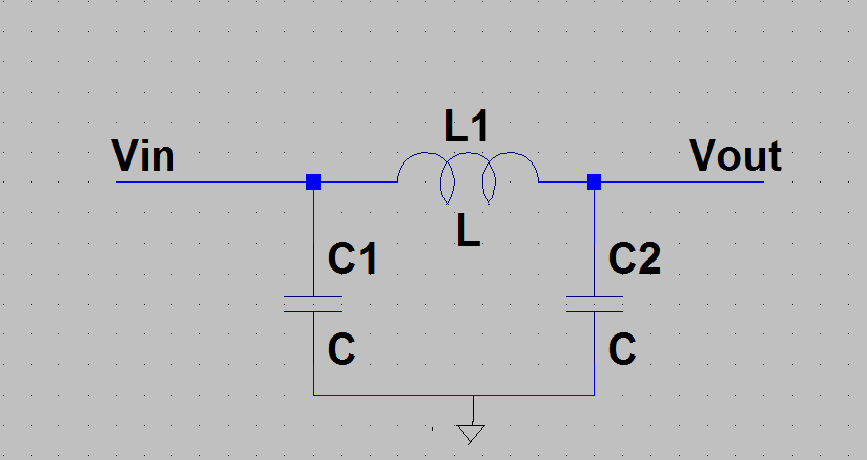
Actually I got confused while deriving the frequency for colpitt's oscillator. The usual way of finding out the frequency is that I equate the imaginary part of the transfer function (of the feedback path) to zero and find out 'ω'. In colpitt's oscillator we have this circuit in the feedback path.


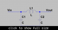
What is the transfer function of the above circuit. I tried it and I get a it to be indepedent of C1 itself!

V0/Vi= 1/(1+s²LC2)

and also there is no imaginary term at all!

Where's the mistake?

Thanks in advance.:?::?::?:
 

Dear iVenky
Hi
If it is a feed back network , you should affect , the effect of input resistance and out put resistance on it . ( it will use with an amplifier to create oscillations ?!)
Anywhere , you can find it's transfer function , with two node . first one in input and the other in out put . isn't it ?
Best Wishes
Goldsmith
 

iVenky,

When I work out the transfer function, I get V0/Vi= 1/(1-s²LC2) . That assumes that Rin in series with Vin is zero and Rout across C2 is ∞. If those resistances are finite, the transfer function becomes much more complicated.

Ratch

Edit: Sorry, the above transfer function should be V0/Vi= 1/(1+s²LC2), just like you computed. Sorry for the misrepresentation. Ratch
 
Last edited:

in your analysis you drive the input with ideal voltage source. Basically, it can drive whatever is in parallel with it (C1) in no time, so C1 has no influence on the frequency response. Since you don't have loss in the circuit you get two imaginary pole on the jw axis.
 

there is no imaginary term at all
Just the other way around, tt's a purely imaginary pole pair, as expectable from a infinite Q LC low pass.

You would want to analyze the circuit with a real source impedance. All technical LC bandpass filter designs are based on real source and or load impedance components.

I think, the question is connected to your LC oscillator thread, which suffers from the same problem: Not considering the LC filter source impedance.
 

Status
Not open for further replies.

Similar threads

Part and Inventory Search

Welcome to EDABoard.com

Sponsor

Back
Top