Welcome to our site! EDAboard.com is an international Electronics Discussion Forum focused on EDA software, circuits, schematics, books, theory, papers, asic, pld, 8051, DSP, Network, RF, Analog Design, PCB, Service Manuals... and a whole lot more! To participate you need to register. Registration is free. Click here to register now.
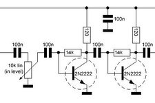
It is to be used in HF as said, so 2-30MHz.
In different pot settings.
A rough estimation is enough. Will be a low impedance, high impedance, how high 1k, 10k or what?
Rough estimation is it will be like most common emitter configurations, middle impedance, probably several hundred Ohms to a few K. That is assuming the pot is omitted or set to maximum. Note that most potentiometers will work badly at 30MHz too.
Rough estimation is it will be like most common emitter configurations, middle impedance, probably several hundred Ohms to a few K. That is assuming the pot is omitted or set to maximum. Note that most potentiometers will work badly at 30MHz too.
Brian, To present a constant input impedance and at the same time allow the pot to adjust the input signal, I was thinking of a stereo pot, say 2x 500 ohms. One gang will be connected as a usual potential divider. Its wiper, will be connected through a 500R resistor to the wiper of the second gand. i.e. the second gang will be connected in reverse.
This will present 500 ohms at the input of whatever stage is to be connected to the amplifier (eg a filter) and 500 ohms to the amplifier input as well. Even at it's high position there will be a 500R series resistor, so the impedance would be somewhat presented.
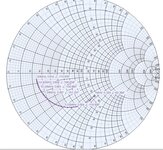
This is the input impedance at various frequencies between 1MHz and 30MHz (reflection coefficient in Magnitude-Angle format) at the transistor base without potentiometer. I think the other measurements are meaningless.
To convert a reflection coefficient in Magnitude-Angle format into Impedance Zs(Rs +/- jXs) format, use the calculator below:
This site uses cookies to help personalise content, tailor your experience and to keep you logged in if you register.
By continuing to use this site, you are consenting to our use of cookies.