Continue to Site

Welcome to EDAboard.com

Welcome to our site! EDAboard.com is an international Electronics Discussion Forum focused on EDA software, circuits, schematics, books, theory, papers, asic, pld, 8051, DSP, Network, RF, Analog Design, PCB, Service Manuals... and a whole lot more! To participate you need to register. Registration is free. Click here to register now.

what is the fuss about negative feedback configuration with opamps?

Status
Not open for further replies.

kidi3

Full Member level 1
Joined
Mar 31, 2013
Messages
98
Helped
0
Reputation
0
Reaction score
0
Trophy points
1,286
Activity points
2,350
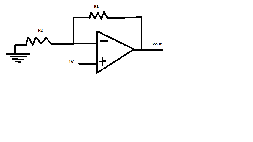
I never quite understood why a negative feedback is so much better than positive feedback.

I know that the usage of it makes it possible to determine the wanted gain, be deciding the resistor values.

But what if i want to amplify a small signal, like an output from an photodiode?..

as i see it the output of the opamp will become negative, which mean that would need some form of inverter to inverter the original output, or have i misunderstood something very basic here?
 

Hi,

Positive feedback generates hysteresis, the output switches from high to low.
Analog/linear output is not possible anymore.

Klaus
 

The polarity of the output from an opamp amplifying a photodode can be positive or negative. Also there ore two ways to do it: Photo-current leakage (light causes reverse leakage current) or photo-voltaic (it becomes a tiny solar cell). An opamp amplifier always has negative feedback.
 

The polarity of the output from an opamp amplifying a photodode can be positive or negative. Also there ore two ways to do it: Photo-current leakage (light causes reverse leakage current) or photo-voltaic (it becomes a tiny solar cell). An opamp amplifier always has negative feedback.

So how do i make the output positive, as I see it, it is the only use case where it seems usable?..
 

The polarity of the output from an opamp amplifying a photodiode can be positive or negative.
Yes. This popular circuit has e.g. positive output.

IV.gif
 

I think you are confusing "inverting" and "non-inverting" with negative and positive feedback. They are entirely different things. An amplifier can invert or not invert when it has positive or negative feedback. Positive feedback is generally only used in oscillators or some comparators because it's regenerative action makes the output tend to 'hit the rails' with an uncontrollable mid voltage region. Negative feedback does the opposite, it reduces the gain and makes the amplifier more stable and predictable.

There is no reason why you can't amplify the output of your photodiode with a non-inverting amplifier with negative feedback. I would question whether or not an inverted output would be a problem anyway, it's usually quite easy to work with signals whichever 'way up' they are.

Brian.
 

Yes. This popular circuit has e.g. positive output.

View attachment 125386


Why is positive and negative connected?
Are you amplifying the difference?

- - - Updated - - -

I think you are confusing "inverting" and "non-inverting" with negative and positive feedback. They are entirely different things. An amplifier can invert or not invert when it has positive or negative feedback. Positive feedback is generally only used in oscillators or some comparators because it's regenerative action makes the output tend to 'hit the rails' with an uncontrollable mid voltage region. Negative feedback does the opposite, it reduces the gain and makes the amplifier more stable and predictable.

There is no reason why you can't amplify the output of your photodiode with a non-inverting amplifier with negative feedback. I would question whether or not an inverted output would be a problem anyway, it's usually quite easy to work with signals whichever 'way up' they are.

Brian.


So i want to trigger on the output from the op-amp. But it just seem silly to flip ones "perception"... I mean if i had a signal go 3µv and i used a inverting amplifier and amplify signal 1000000 times, i would get a signal which is -3 v, and trigger based on that..

Why not use a positive feedback and then trigger if the value is 3v?

I might have misunderstood something here.. But this is what makes no sense, i don't quite see the benefit of using negative feedback. I would always use positive, as the polarity of v_out would always follow the polarity of v_in.. It makes no sense (for me at least) to use negative feedback and flip the polarity between v_in and v_out..
 

Hi,

Why is positive and negative connected?
Are you amplifying the difference?

You should read about Opamps.

--> yes, every Opamp is designed to amplify the difference between the two inputs,
--> And therefore, yes, you always need to connect both inputs.

These are the most common basics of Opamps.

The circuit of your post8 is named "transimpedance amplifier" it converts the current caused by the photodiode into voltage.
The ratio of U/I is given by the feedback resistor.

The circuit is well suited for photodiode operation, because the constant voltage across the photodiode it eliminates the negative effects of the relative big photodiode capacitance.

Klaus
 

I might have misunderstood something here.. But this is what makes no sense, i don't quite see the benefit of using negative feedback. I would always use positive, as the polarity of v_out would always follow the polarity of v_in.. It makes no sense (for me at least) to use negative feedback and flip the polarity between v_in and v_out..

Yes - there is a severe misunderstanding on your side.
What is the result of positive feedback?
Answer: A certain fraction of the output voltage is fed back to the input and supports the input signal (is added to the input and, thus, further increases the input signal).
As the result, the output goes higher - and this increase again is fed back and further increases the input.
I suppose, now you can expect what happens: The output goes higher and higher until it is limited by the supply voltage. Result: saturation.

Therefore: Linear operation (amplification) is NOT possible for positive feedback; stable operation requires negative feedback.

Thanks LvW - It makes totally sense :)
But still, negative feedback drive the input to near 0, but provide a more controllable amplification. but how is the issue with the output dealt with. I mean it can't be right that the sign is flipped and thats it?, It just seem too inconvenient to work with to be true...
 
Last edited:

Hi,

But still, negative feedback drive the input to near 0,
No. Not always 0. If you have input voltage you will see output voltage.
U_out = GAIN x U_in. (With negative feedback GAIN can be negative as well as positive), U_in is the differential input voltage (U_in+ - U_in-)

Negative feedback just generates a calculable gain. So output voltage depends on feedback and input voltage.

***

Read about OPAMP circuits.

1) standard inverting circuit. (Inverting means negative GAIN)
It uses negative feedback (A resistor from OUTPUT to IN-)
It uses a second resistor for GAIN setup( A resistor form signal input to IN-) . Becuase the signal comes (via resistor) to the IN- it generates a negative GAIN.
GAIN = - Rf / R2 (you see GAIN is negative, with either value of Rf and R2)

2) standard non iverting circuit (non inverting means positive GAIN)
It uses the same negative feedback resistor as the inverting circuit (A resistor from OUTPUT to IN-).
It uses a second resistor for GAIN setup (A resistor from GND to IN-). The signal now goes to the IN+ and thus it generates positve GAIN. (but also with negative feedback)
GAIN = 1 + (Rf / R2) (you see GAIN is positive, with either value of Rf and R2)

Klaus
 

I will take advantage of this thread and ask you guys a question which I had since I started learning the OP amps.

They say that for an ideal OP amp, the gain in open loop is infinity, so the IN- and IN+ are equal.

What I don't understand is how in a closed loop, for example the inverting or non-inverting OP amp as Klauss said above, has finite gain.
 

What I don't understand is how in a closed loop, for example the inverting or non-inverting OP amp as Klauss said above, has finite gain.

Simple example:
* Non-inverting configuration with Vin=1V at the pos. (non-inv.) input.
* Open-loop gain of the amplifier: Ao=100 (for a simple calculation)
* Feedback factor (voltage divider between output and inv. input) k=0.099
* Diff. voltage: 1-0.099=0.01V
* Output: 0.01*100=10V.
* Result: Amplifier with a closed-loop gain of 10.

OK?
 
Last edited:
  • Like
Reactions: CataM

    CataM

    Points: 2
    Helpful Answer Positive Rating


This is the confinguration we are referring right?

If V-=0.01 and V+=1 => Vout=(1-0.01)100=99 V
 

Many people on these forums are confused by the term "negative gain" because they think it is signal loss and not gain. It should be called "gain with an inverted output" then they should be told that inverted means that when the input goes positive then the output goes negative and vice-versa.
 
  • Like
Reactions: CataM

    CataM

    Points: 2
    Helpful Answer Positive Rating


This is the confinguration we are referring right?

If V-=0.01 and V+=1 => Vout=(1-0.01)100=99 V

Read agian my post. (Vdiff=0.01V)
 
  • Like
Reactions: CataM

    CataM

    Points: 2
    Helpful Answer Positive Rating
You have a very serious misunderstanding of the basic principles of an opamp (an amplifier in general).

An ideal OPAMP has infinite open loop gain; any small voltage diff between the -/+ terminals will have a very large output (reach the supply voltage with practical OPAMPS).

In any real circuit, the -/+ input terminals are at virtual ground. Therefore you must connect your input to these two terminals via some resistor.

To get a finite amplification, you need to use negative feedback. It is done by sending a part of the output to the inverting input of the amplifier. The gain is now determined by the proportion of the output being fed into the inverting input and is independent of the OPAMP. This is the key idea of an amplifier. If you look into the formula for gain, it is set by resistors and can be rather typical values like 1, 10 or 100 or even 1000. If you want a gain of 10^6, you need to consider other parameters of the OPAMP (you do not need a gain of 10^6, right?)

If you feed a part of the output into the non-inverting input, the output will quickly saturate and reach -/+ Vsupply. This can be used in some applications but not as amplifier.

To understand why we need negative feedback (and not positive feedback) to stabilize the output, you need to understand the concept of virtual ground. If you need to amplify a small signal, like the output of a photodiode, you need to consider several other factors. One of them is the gain vs bandwidth. Let us postpone that for a later discussion.
 
  • Like
Reactions: CataM

    CataM

    Points: 2
    Helpful Answer Positive Rating
Status
Not open for further replies.

Similar threads

Part and Inventory Search

Welcome to EDABoard.com

Sponsor

Back
Top