T
Continue to Site
Follow along with the video below to see how to install our site as a web app on your home screen.
Note: This feature may not be available in some browsers.
....datasheet doesnt say.
As VICOR white paper explains...
 www.allaboutcircuits.com
If my question I'd buy samples from different manufacturers and test.
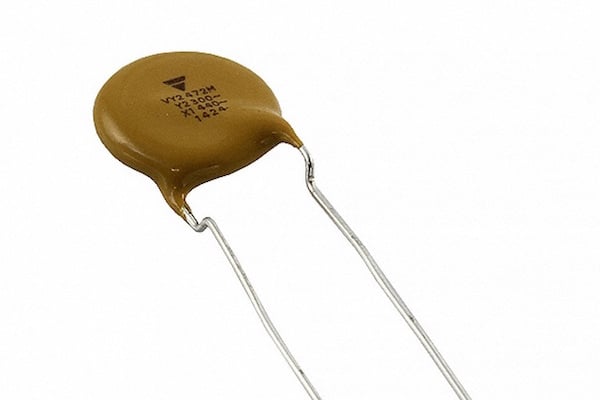
Leakage currents graph: all caps have a parallel resistance, for
2.2nF and 500Vac I_leak expected below approx. 300uA.
The so called XY safety ratings standard is just a half-way job because Voltages alone do not overheat or burn things: It’s a combination of enough Voltage and enough current, Amperes burn things.