Continue to Site

Welcome to EDAboard.com

Welcome to our site! EDAboard.com is an international Electronics Discussion Forum focused on EDA software, circuits, schematics, books, theory, papers, asic, pld, 8051, DSP, Network, RF, Analog Design, PCB, Service Manuals... and a whole lot more! To participate you need to register. Registration is free. Click here to register now.

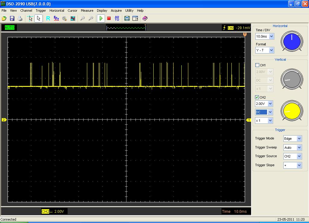
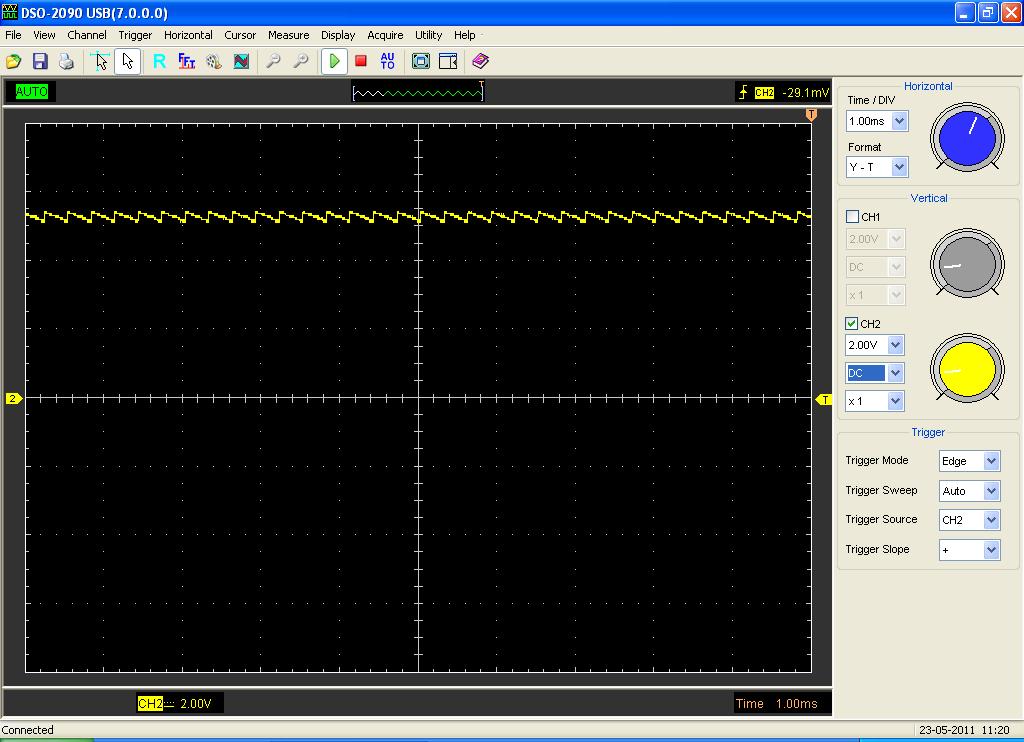
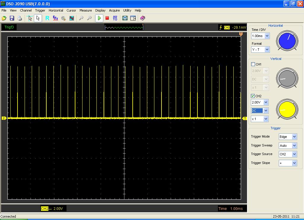
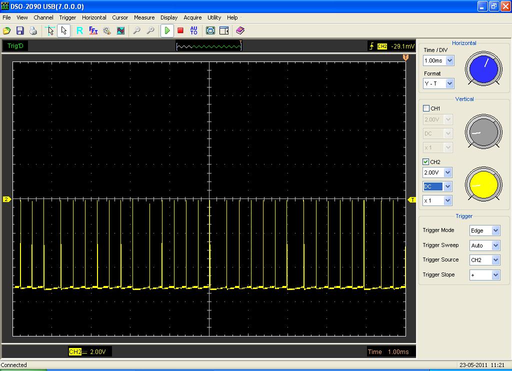
What is the correct voltage/signal/shape on the charge pump capacitors?

Status
Not open for further replies.
Re: MAX3232 charge pump?

I haven't seen the voltages on an oscilloscope but I remember that the voltage at the pins of the chip (where the capacitors are connected) were stable.

Alex
 

Re: MAX3232 charge pump?

Here is what I see....

C1+ basically is at 3v and pulses up to 5.5v giving two 1uS pulses every 35uS

C1- basically is at zero and pulses up to 3v in the same way as above

C2+ is at zero and pulses up to 5.5v in the same pattern

C2- is at -5.5v (negative) and pulses "up" to -0.5v in the same pattern
 

Re: MAX3232 charge pump?

When the capacitors are connected you will not be able to observe these because once the capacitors are charged the voltage will be kept at a steady level.
Have you measured these with the capacitors connected ?

Alex
 

Re: MAX3232 charge pump?

You mean to say that the attached images are proper?


When the capacitors are connected you will not be able to observe these because once the capacitors are charged the voltage will be kept at a steady level.
Have you measured these with the capacitors connected ?

Alex
 

Re: MAX3232 charge pump?

The images with the saw tooth pulses are normal for a capacitor as it charges/discharges, I guess depending on the load and the size of the capacitor the amplitude can change.
The other images with the narrow sharp edges look strange but I don't know if they should be like that or not, especially in your first image the rate of these narrow edges is not periodic.

Alex
 

Re: MAX3232 charge pump?

Sorry I thought the file names would carry over. The images with the "spikes" are from the charge pump capacitors, C1 and C2 (at both ends). Seems strange to me, but also I don't know what they should look like since I could not find a reference.

Another thing is that the voltages on the RS232 side seem to be only +/-6v and not +/-12v. Strange.

Lastly and not exactly related to this, should I have a pull-up resistor on the Tx lines (either TTL side and/or RS232 side) and a series resistor on the Rx input? I have seen this done.


The images with the saw tooth pulses are normal for a capacitor as it charges/discharges, I guess depending on the load and the size of the capacitor the amplitude can change.
The other images with the narrow sharp edges look strange but I don't know if they should be like that or not, especially in your first image the rate of these narrow edges is not periodic.

Alex
 

Re: MAX3232 charge pump?

I haven't seen or used any pull-up resistor or RX series resistor with MAX232 or MAX3232 and I don't see the point of using them.
Do You have a problem with the operation of the chip, isn't the signal recognized properly form the PC?

Alex
 

Re: MAX3232 charge pump?

@blapcb, you wouldn't normally use the signals on these pins.
The scope traces make no sense unless you tell us where your reference pont is. If you are measuring from ground, where is the negative rail? Is this a simulation or real hardware?
The data side of the interface has active drivers, there is no need to use a pull-up resistor.

Brian.
 

Status
Not open for further replies.

Similar threads

Part and Inventory Search

Welcome to EDABoard.com

Sponsor

Back
Top