Continue to Site

Welcome to EDAboard.com

Welcome to our site! EDAboard.com is an international Electronics Discussion Forum focused on EDA software, circuits, schematics, books, theory, papers, asic, pld, 8051, DSP, Network, RF, Analog Design, PCB, Service Manuals... and a whole lot more! To participate you need to register. Registration is free. Click here to register now.

What is the best way to measure main voltage with isolation

Status
Not open for further replies.

rprodrigues

Member level 2
Joined
Nov 18, 2006
Messages
49
Helped
0
Reputation
0
Reaction score
0
Trophy points
1,286
Location
Itajubá MG Brazil
Activity points
1,653
measure mains voltage isolated

Hello,

What is the best way to measure main voltage with isolation?

Any suggestions ?


Thank you
 

measurement accuracy need voltage

Are you re-scheduling your question because you don't like the answers you received? It's unwanted crossposting anyway.
 
Re: What is the best way to measure main voltage with isolat

FvM said:
Are you re-scheduling your question because you don't like the answers you received? It's unwanted crossposting anyway.

No. I am not.

Actually, I do need to know what is the best way to measure the main voltage and that was the point of the question at this thread.

The other thread was related to the ways used to measure, and not the best one.
 

I think, the question should be better appended to the first thread. Anyway, the method I suggested as most economic is also considered the "best" in many fields of electrical engineering. But obviously, the criteria for "best" can be quite different, e.g. isolation safety, achievable overvoltage category, self-powered operation, bandwidth, phase error, amplitude error, size, temperature range, DC capability, required output signal and more.
 
Re: What is the best way to measure main voltage with isolat

FvM said:
I think, the question should be better appended to the first thread. Anyway, the method I suggested as most economic is also considered the "best" in many fields of electrical engineering. But obviously, the criteria for "best" can be quite different, e.g. isolation safety, achievable overvoltage category, self-powered operation, bandwidth, phase error, amplitude error, size, temperature range, DC capability, required output signal and more.


FvM,

you are right. The question could be appended to the first thread. I am sorry for making it a mess.

By the way, what I am looking for is a voltage "transducer" to be used in domestic single-phase power (energy) meter, so the isolation safety is a requeriment. Any suggestion ????


Thank you
 

A divorced-winding transformer is not bad for safety,
pretty waveform-accurate but unlikely to be compact.
Your AC-DC conversion would be the likeliest error
source.

Optoisolators are similarly good for isolation, you may
embed some error in simple circuits but a decently low
error could be had from a closed loop, off-line powered
circuit block (think one op amp, two optoisolators
that are type-matched and one is used as feedback
while the other is forward). Converting voltage to
frequency or duty cycle and feeding back the average
might remove analog nonidealities of the opto.

For power metering a dissipative current /power
sense element and a temperature sensor (or pair
for thermal flux) are also viable. This approach may
be closer to true RMS if the waveform is irregular.
But if there is an off-unity power factor, it probably
needs both voltage and current sensed (as do the
other approaches).

I don't know what your "design values" are, as far
as accuracy.

I would be surprised if there weren't already chip
solutions out there at tens of cents a pop, for this
purpose (using one of the above for isolation). But
speaking of isolation, how much? Modest levels may
be on-chip-practical, but 10kV means a few mm of
plastic is probably involved, somewhere.
 
Re: What is the best way to measure main voltage with isolat

FvM already answered your question: the most economical (and secure) way is to use a transformer.
If you really need high insulation, there are specific devices (transformers) with much higher insulation voltage than the default ones.
In my work we use some small custom wound transformers to do exactly what you want.
Their price is really low and we were able to pass the most important tests (UL, CE, ...) without any trouble.
 
Re: What is the best way to measure main voltage with isolat

In my opinion, it's not easy to achieve the performance of a measuring transformer with other isolation techniques. Among the pure analoge methods, only DC magnetic (hall sensor) current transducers with feedback loop have an acceptable accuracy. V/f or PWM transducers (with optical or inductive isolation) aren't bad, but involve complex circuits.

The best method for high resolution, high bandwidth and DC capable isolated voltage measurement is digital acquisition at the input potential and digital transmission. That's also the usual way to operate an electronic energy meter. Typically only the external data interface (e.g. M-BUS) is isolated.
 
Hi all.

After all aid received, I decided to go with a transformer.

My application needs to measure 110V and 220V and translate as 5V at the measuring circuit side.

Could you suggest me some good transformers (model and/or supplier) for this purpose, please?

Thank you again!
 

Without knowing particular specifications, I would say that a standard low power (0.3..4 VA) print transformer should do.
 
Re: What is the best way to measure main voltage with isolat

Rather strange as question: we even do not know where do you live!
There are LOTS of things to be taken in account before making such choice; some of them are:

1) how many pieces/year do you need
2) which certifications does your device require (UL, CE, BS, ...). Which safety norms do you must follow?
3) which circuit/method will you use to read the voltage and its precision/distortion/bandwidth requirements
4) min/max dimensions
5) max price/unit
6) Class of insulation and safety class of the transformer
7) ...

Once you have answered to those questions, maybe we can be of some help.
Please remember that sometimes is cheaper to use custom products (ask to local transformer producers), sometimes it is better to buy ready made [COTS] components (see your typical local distributors: RS, Farnell, Digikey, Mouser, ...)

At this date your requirements are too vague to give you ANY answer.
 
Re: What is the best way to measure main voltage with isolat

bepobalote said:
Rather strange as question: we even do not know where do you live!
There are LOTS of things to be taken in account before making such choice; some of them are:

1) how many pieces/year do you need
2) which certifications does your device require (UL, CE, BS, ...). Which safety norms do you must follow?
3) which circuit/method will you use to read the voltage and its precision/distortion/bandwidth requirements
4) min/max dimensions
5) max price/unit
6) Class of insulation and safety class of the transformer
7) ...

Once you have answered to those questions, maybe we can be of some help.
Please remember that sometimes is cheaper to use custom products (ask to local transformer producers), sometimes it is better to buy ready made [COTS] components (see your typical local distributors: RS, Farnell, Digikey, Mouser, ...)

At this date your requirements are too vague to give you ANY answer.


This is my first work within this area, so I do not have so many requirements.

Anyway, here are some answers:

1) how many pieces/year do you need
- Just a few, since it is going to be a prototype;

2) which certifications does your device require (UL, CE, BS, ...). Which safety norms do you must follow?
- None of them. The main purpose is to build a cheap circuit.

3) which circuit/method will you use to read the voltage and its precision/distortion/bandwidth requirements
- I plan to pass the outup signal to a low-pas filter and send it directly to an ADC input. Up to 50*60 Hz bandwith is enough and the precision may be of 0.1%, for example.

4) min/max dimensions
- As small as possible.

5) max price/unit
- The cheapeast possible.

6) Class of insulation and safety class of the transformer
- It is not a problem for now. I will not care about it right now.


By the way, do you suggest me any norm to follow since it is going to be for domestic use in Europe (IEC norm?) ?

As you can see, I am a little confused about what transformer I need, so I'd like to post some others questions:

1 - Here is some transformers I've found http://www.hahn-trafo.com/english/pcb-transformers-bv20.php. Would the BV 201 0128 one be ok for me?

2 - Should I look for an "instrument" transform?

3 - Does "print transformer" mean a PCB transform ?

4 - Is there any kind of transformers (high precision, low secondary voltage, etc) for using in power meters (energy meters)? What are the manufactures most known internationally ?


Thank you again!
 

Re: What is the best way to measure main voltage with isolat

Sorry for the plethora of questions, but as you can imagine...
Because of your requirements, you have to surely use a ready made transformer.

It seems you are living in Europe so, just as an example, I think you can check
https://www.rs-components.com/index.html
and take a look at the following component (RS) codes:
310-1178
310-1241

In general all of those transformers (like the ones you have found) have all the right safety markings to be considered to be safe in almost any applications (except for medical devices).
Unfortunately now I'm not at the office so I can't give you SOME references to the safety norms to be followed when designing with mains voltage. Please remember that the price of those norms is not cheap for a "casual" user! :cry:

Some suggestions for transformer usage:

1) You have to slightly load the secondary of your transformer with a resistor load. Choose it with the right value and wattage to give a 20-30% of load. Do not leave it "open circuit"
2) You surely have to reduce the output voltage of the transformer: it is higher than your 5 or 3.3V max of your ADC. Define your partition resistances in such way that even with an input of 300Vac you will not overload your ADC. Take care of your ADC input impedance when you compute the values.
3) I think you have to rectify (diodes) your transformer output: you can use a full bridge so you will be able to measure all of the half sine of the input waveform. Otherwise you can use an "half voltage" reference to which you can add the output of the transformer: your voltage will vary between 0V and 5V with 2.5V== 0Vac.
4) if you are using diodes to rectify the transformer output, please remember that they start to conduct at 0.7V (Si): if your measure must be precise, you need to take in account this.
5) What are you requirements on measure? do you want true RMS values? Is the input voltage real sinusoidal or is distorted? Your method of measurement can be completely different depending of your needs.

- - -
Answers to your questions:
1) it seems OK
2) From what you wrote, I really do not think so!
3) I think so
4) This one is a completely different beast! If you need to measure power you have to use different devices: current transformers (TA), hall effect sondes, ...
You can take a look to the website of one of the best producers: https://www.lem.com/ as an example you can check their **broken link removed**: in some situations it can be really neat!!
 
Re: What is the best way to measure main voltage with isolat

I simply skip the question of further signal processing by assuming an existing electronic energy meter circuit, e.g. an Analog ADE77xx. In this case, you have effectively no load to the transformer, unless you introduce it intentionally.

Although these advanced metering circuit also offer an option for phase calibration, you may want to avoid systematic phase errors by design. This means, that the transformer should be better operated open circuit, respectively with a small load, I think. Although this is different from usual specified instrument transformer operation, it reduces the phase error and achieves an output voltage according to the winding ratio, except for a small voltage drop at the primary caused by the core's magnetization current. These quantities can be calculated and more or less accurately predicted, if you are interested in.

As I already mentioned before, electronic energy meters usually avoid voltage isolation transformers by operating the measuring circuit at mains potential.
 
Re: What is the best way to measure main voltage with isolat

Only now (my fault) I get that you require a 0.1% precision in your voltage measurements...
I' m not sure it will be so easy with a simple transformer and in a cheapest way to reach such precision.
Depending on the construction process/materials of the typical transformers, you can assume to get at least 1-2% of error in the output voltage.
Are you sure you need such precision?
If yes, I think you have to try different way to get your measures (eg: resistor network + ADC + optoinsulator).

Just as an example, the evergreen Fluke 45, a 6.5 digit multimeter has a precision of +-0.2% on the Vac measurements!
Maybe you will be compelled to use as your reference an instrument like the Agilent 3458A (base price 8000 USD).
The same is for the stability of your Vac generator needed to calibrate your circuit!
Your requirements are rather tight!
 

Re: What is the best way to measure main voltage with isolat

I think bepobalote is basically right regarding accuracy limits with simple transformers. The situation is different however, if the voltage response and also the phase error of the instrument's voltage channel can be adjusted or not.

Usually an instrument transformer is expected to have a specified voltage transmission ratio, it's accuracy is directly contributing to the measurement's overall accuracy. A catalog general purpose transformer has no specified voltage ratio, you must determine it yourself and can provide an adjustment. A more difficult point are phase errors, frequency response and voltage/temperature dependency of parameters.

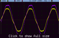
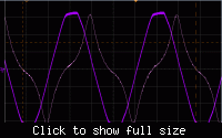
I checked with a Hahn BV EI 303 2030 (6V/1.9VA). The most limiting factor for accuracy is the nonlinear magnetization current and the output voltage distortion and phase error caused by it. In a short, you get negative phase shift of output voltage, that is almost unaffected by a resistive load. Altough the phase error can be calibrated, it must be clearly voltage dependant. To get rid of this error, the transformer must be operated at a lower flux, e.g. 115 instead of 230 V input voltage. Unfortunately, you don't get small catalog transformers designed for higher input voltage, so you a custom specific design would be required, as bepobalote suggested.

There is possibly an option, to operate the transformer with a voltage divider at the primary, but it has to be designed carefully and involves higher losses anyway. I suggest to extract the transformer equivalent circuit parameters from a measurement and play around with different circuit options.

Primary Voltage (100 V/div) and Magnetization current (10m A/div)


Primary Voltage (100 V/div) and Secondary Voltage (5 V/div)
 

Re: What is the best way to measure main voltage with isolat

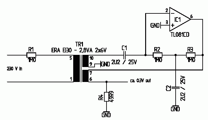
A possible method, to reduce transformer inherent errors is to operate it as current transformer in a feedback loop with zero
total flux. The principle circuit showed good behaviour in simulation with realistic transformer properties.

Principle circuit of an AC voltage transducer based on a feedback operated current transformer
81_1253378474.gif
 
Re: What is the best way to measure main voltage with isolat

@ FvM and bepobalote:

You are the "ones".


I thought a simple transformer could to the job for me, but you have shown me that there are more things I should take care then I thought it was.

This way, I am sure that the 0.1% precision requirement must be dropped and I may go with a measuring circuit operating at mains potential and with the use of an electronic energy meter circuit (maybe the CS5463 from Cirrus).

Do you think that an opto-isolation between the the measuring circuit and the user interface circuit could keep all the isolation for safety ?


All the suggestion regarding the transformers and its difficulties were great!!! :D


Thank you!
 

I must confess, that I expected a better performance with standard (catalog) transformers. But I generally prefer isolation in the digital domain, that also offers DC capability and higher bandwidth.

Digital isolators with 5 kV/1 min rated insulation voltage are good for 300 VAC Cat IV respectively 450 VAC Cat. III, which should be sufficient for all installation requirements.
 
i want a transformarless transforming circuit which will help me get 5v from 230v(both AC).

pleas help me.
 

Status
Not open for further replies.

Part and Inventory Search

Welcome to EDABoard.com

Sponsor

Back
Top