Continue to Site

Welcome to EDAboard.com

Welcome to our site! EDAboard.com is an international Electronics Discussion Forum focused on EDA software, circuits, schematics, books, theory, papers, asic, pld, 8051, DSP, Network, RF, Analog Design, PCB, Service Manuals... and a whole lot more! To participate you need to register. Registration is free. Click here to register now.

what is Single edge control and double edge control in PWM LPC2148

Status
Not open for further replies.

embpic

Advanced Member level 3
Joined
May 29, 2013
Messages
742
Helped
80
Reputation
160
Reaction score
77
Trophy points
1,308
Location
india
Activity points
5,213
Hello master's
i am using lpc2148 processor and keil compiler.i started to work on PWM on processor.after reading data sheet this point is not clead to me that
what is single edge controlled output and double edge control output?
 

You can relate the difference to using a sawtooth versus a triangle carrier waveform in analog pwm generation, which reults in trailing edge versus double edge modulation. Technical multiphase PWM systems, e.g. motor inverters are mostly using double edge modulation, resulting in lower pwm frequent ripple current.
 

and where are the single pwm modulation is used?
and in single modulation state remain same means remain HIGH or remain LOW
and in double it change the state
is it correct?
 

I don't know what you mean with "single pwm". We have been talking about single/dual edge control respectively modulation.

If you are asking about meaningful applications of single edge control in LPC2148, it starts all pwm pulses at the same time, so it's inappropriate for most multi-phase applications. The question can be better discussed referring to real PWM applications and their requirements, e.g. how many independent PWM signals must be generated.
 

ok sorry for that i meant to say single edge mode.
i have doubt that if we are using single timer for all pwm's then, can we set freq for each pwm if i wish to drive any load?
 

For both LPC2148 PWM modes, same frequency of all outputs is presumed.
 

ok sir but in my application i have to use three stepper motor. so if i want to drive these stepper motor simultaneously, but i have to drive each steeper motor with different freq. then is it possible with PWM. or i have to use two timer and PWM timer for three stepper motor.
 

i don't think that the LPC2148 PWM module is particularly suited for stepper motor control.
 

single edge control means the the output will be high from match of match 0 and low at particular match...

Double edge control means you can control both positive rising and negative rising and the match 0 doesn't involves in operation (match 0 is common for all single edge controlled PWM outputs).. Match 2 and match 1 is used for pwm 2 in double edge mode.... (pwm 1 is single edge controlled only)...
 

thank you sir means if i want to use single edge control pwm then i have six option and if double edge then three output that is pair of registor for one double edge output.
 

yes but small correction....

there are totally 6 pwm outputs the PWM1 is only single edge controlled and the remaining are both mode possible

single edge mode,
pwm1 match 0 rising edge match 1 falling edge
pwm2 match 0 rising edge match 2 falling edge
pwm3 match 0 rising edge match 3 falling edge
pwm4 match 0 rising edge match 4 falling edge
pwm5 match 0 rising edge match 5 falling edge
pwm6 match 0 rising edge match 6 falling edge

Double edge mode,
pwm2 match 1 rising edge match 2 falling edge
pwm3 match 2 rising edge match 3 falling edge
pwm4 match 3 rising edge match 4 falling edge
pwm5 match 4 rising edge match 5 falling edge
pwm6 match 5 rising edge match 6 falling edge

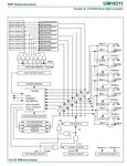
you can refer the block diagram for very better understanding......
attachment.php
 

Attachments

  • untitled.JPG
    untitled.JPG
    84.3 KB · Views: 472
  • Like
Reactions: embpic

    embpic

    Points: 2
    Helpful Answer Positive Rating
ok sir got the idea means i can select any three pair from double edge control from list u mention
for individual output.
and Match0 provide PWM cycle rate which will common to all PWM's output.
 

Yeah you can and don forget to make match 0 the highest value and make TC to reset on Match 0 with Match control register...

- - - Updated - - -

with PWM you can alter the ON time and OFF time of the diff pwm outputs and not the frequency so what are you going to do with stepper motor???

Do you know about external match outputs MATm[n] pins they are run by diff timer modules may be you can use them....
 

as per written in datasheet PWM part and latch enable registor what does it mean?
At that point, the new
values will take effect and determine the course of the next PWM cycle. Once the transfer
of new values has taken place, all bits of the LER are automatically cleared. Until the
corresponding bit in the PWMLER is set and a PWM Match 0 event occurs, any value
written to the PWM Match registers has no effect on PWM operation.

means i have to set again and again latch enable registor when it cleared!!

- - - Updated - - -

sir i am using keil4 compiler. how to assign pin number in analysis window in debug mode. to observe the pin behavior.
thanx

- - - Updated - - -

yes sir i have successfully done double edge mode but without interrupt.
but sir mt quetion is remain as
how to assign pin number in analysis window in debug mode. to observe the pin behavior.
thanx
 

Status
Not open for further replies.

Part and Inventory Search

Welcome to EDABoard.com

Sponsor

Back
Top