Continue to Site

Welcome to EDAboard.com

Welcome to our site! EDAboard.com is an international Electronics Discussion Forum focused on EDA software, circuits, schematics, books, theory, papers, asic, pld, 8051, DSP, Network, RF, Analog Design, PCB, Service Manuals... and a whole lot more! To participate you need to register. Registration is free. Click here to register now.

What is RFC for in this mixer?

tony_lth

Advanced Member level 5
Joined
Jul 28, 2010
Messages
2,086
Helped
377
Reputation
756
Reaction score
368
Trophy points
1,363
Location
Beijing
Activity points
12,623
Hi, Gurus,
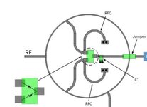
I met this mixer circuit, as the following picture.
I have several questions:
1. What is the RFC for?
2. If for matching the input of diodes, why it is in the root of the pin? And the diodes input impedance should be varied by the freq and input LO power level, right?
Best,
Tony Liu
 

Attachments

  • Mixer_Issue_1.JPG
    Mixer_Issue_1.JPG
    27 KB · Views: 79
 

    tony_lth

    Points: 2
    Helpful Answer Positive Rating
In the attachment report, it showed the conversion loss when IF=1Hz, 100Hz. How can they do so?
I guess they tested in Radar, but how to calibrate the test system?
Best,
Tony Liu
 

    tony_lth

    Points: 2
    Helpful Answer Positive Rating
"using two signal generators", that's what I am curious.
It sounds impossible to find IF=1Hz for two signal generators.
So they should test in radar.
 
I don't know where you see 1Hz. Minimum shift frequency in Fig.10 is 10Hz.
Anyway, to test with accuracy in a radar, and to don't do this in a field, they may use a Doppler (velocity) emulator, which are pretty expensive devices.
But two signal generators (one for RF and one for LO) connected both to the same reference (10MHz let's say) may do the job.
 

    tony_lth

    Points: 2
    Helpful Answer Positive Rating

LaTeX Commands Quick-Menu:

Part and Inventory Search

Welcome to EDABoard.com

Sponsor

Back
Top