Continue to Site

Welcome to EDAboard.com

Welcome to our site! EDAboard.com is an international Electronics Discussion Forum focused on EDA software, circuits, schematics, books, theory, papers, asic, pld, 8051, DSP, Network, RF, Analog Design, PCB, Service Manuals... and a whole lot more! To participate you need to register. Registration is free. Click here to register now.

What is operating frequency of BD 139

Status
Not open for further replies.

deepakchikane

Full Member level 3
Joined
Jul 17, 2012
Messages
178
Helped
2
Reputation
4
Reaction score
2
Trophy points
1,298
Location
Mumbai, Maharashtra, India, India
Activity points
2,623
Hi all,

i would like to know the operating frequency of BD 139.

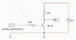
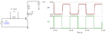
I am generating 30 khz signal from a controller & driving a bjt bd 139 for current amplification purpose.

i have biased the bd 139 to maintain a voltage between B-E terminals.
but the bd 139 is giving a signal for more time than actual controller signal.

datasheet:https://www.st.com/web/en/resource/technical/document/datasheet/CD00001225.pdf

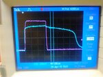
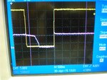
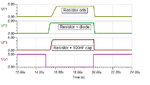
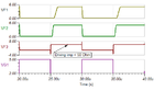
check the attached image
1) pink is the waveform from controller.(5v)
2) Blue waveform is at the actual bjt pin (gnd to base of bd 139)
biasing resistor is 400 ohms.
 

Attachments

  • DSC_0741.JPG
    DSC_0741.JPG
    872.1 KB · Views: 137

The BD139 is good to much higher frequency, I have used them at 20MHz with no problems. It seems something is wrong with the circuit driving the base pin, can you post your schematic so we can see please.

Brian.
 

Schematic please! Saying it's "like a switch" doesn't tell us anything. It appears that whatever drives the bias resistor is not able to sink current to remove that bias.

Brian.
 

When the drive pulse appears the Vc falls on the transistor. When the base drive falls to 0V, the Vc rises and because of the internal capacitance of the transistor raises the base voltage. Try reducing the base driving impedance, to discharge this capacitance faster.
Frank
 

Following experiments done with the bc 547.

here also there is time difference while going high to low.

this makes us problematic at 100 khz.

feedback/suggestions welcome.

Thanks
 

Attachments

  • DSC_0743.JPG
    DSC_0743.JPG
    942.4 KB · Views: 127

I suspect your signal source has a relatively high impedance. What you are seeing is the effect of the capacitance of the base to emitter junction holding charge. It's a bit like adding a capacitor across the signal, it takes a short time to charge up and a slightly longer time to discharge. What you need is a path for that capacitance to discharge quickly so the voltage drops faster. In very high speed applications it isn't uncommon to see resistors of only a few Ohms between the base and emitter to ensure fast switching times. The problem obviously gets worse as the frequency increases but it should work at much higher speeds than 100KHz.

You have three options:

1. reduce the value of the base resistor even further and hope the signal source can sink more current when it is low and supply more when it is high.
2. add a resistor across the base and emitter to provide a discharge path but be aware this will also increase the drive current needed.
3. use an additional driver circuit to increase the available bias currents.

Brian.
 
You can also try to speed up the turn-off by adding a reverse diode. This will only be effective if the driving impedance is low enough.
 

Attachments

  • bd139_drive.png
    bd139_drive.png
    14.6 KB · Views: 168
This diode will work to many MHz no problem.
 

The diode allone won't speed up transistor switching much (only quite a bit by working of it's junction capacitance) , you'll either need a negative input voltage or a capacitor parallel to the base resistor. A schottky diode would have a better effect.
 

By comparison, the diode appears to have a noticeable effect on the turn-off time similar to using a speed-up capacitor solution.

If the driving impedance is low enough, which seems not to be the case in his situation, the capacitor method could give better switching speeds if you are willing to accept possible edge spikes in the output waveform.

- - - Updated - - -

Here in the last plot it shows faster switching speed using the capacitor with driving impedance 25 Ohm.
 

Attachments

  • switch_speed.png
    switch_speed.png
    12.9 KB · Views: 135
  • low_imp.png
    low_imp.png
    10.4 KB · Views: 136
Last edited:

A small capacitor of s few 100 pF gives best results.To supress the negative output spike, add a series resistor of e.g. 100 ohm. But I agree that 1N4148 doesn't perform bad as well.

When designing a real circuit, we must look for the available generator source impedance.
 

I have found from experience that it takes a fairly large value of capacitance to have a worthwhile effect.
Here with a 100 pF capacitor and 25 Ohm driving impedance, there is almost no difference from using just the resistor.
 

Attachments

  • 100pF.png
    100pF.png
    9.8 KB · Views: 139

Status
Not open for further replies.

Similar threads

Part and Inventory Search

Welcome to EDABoard.com

Sponsor

Back
Top