Continue to Site

Welcome to EDAboard.com

Welcome to our site! EDAboard.com is an international Electronics Discussion Forum focused on EDA software, circuits, schematics, books, theory, papers, asic, pld, 8051, DSP, Network, RF, Analog Design, PCB, Service Manuals... and a whole lot more! To participate you need to register. Registration is free. Click here to register now.

What is K factor in increasing the power factor ?

Status
Not open for further replies.

dineshdeshmuk

Full Member level 5
Joined
Sep 12, 2011
Messages
285
Helped
18
Reputation
36
Reaction score
18
Trophy points
1,298
Activity points
3,131
What is K factor in increasing the power factor ?
 

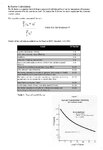
K-factor is a weighting of the harmonic load currents according to their effects on transformer heating,
as derived from ANSI/IEEE C57.110.
A K-factor of 1.0 indicates a linear load (no harmonics).
The higher the K-factor, the greater the harmonic heating effects.

When a non-linear load is supplied from a transformer, it is sometimes necessary to derate the transformer
capacity to avoid overheating and subsequent insulation failure.
The reason for this is that the increased eddy currents caused by the harmonics increase transformer losses
and thus generate additional heat. Also, the RMS load current could be much higher than the kVA rating of
the load would indicate. Hence, a transformer rated for the expected load will have insufficient capacity.
The K-Factor is used by transformer manufacturers and their customers to adjust the load rating as a function
of the harmonic currents caused by the load(s).
Generally, only substation transformer manufacturers specify K-factor load de-rating for their products. So,
for K-factors higher than 1, the maximum transformer load is de-rated.

K-Factor Calculation
The K-factor is a number derived from a numerical calculation based on the summation of harmonic
currents generated by the non-linear load. The higher the K-factor, the more significant the harmonic
current content.

K_Factor_pri.jpg
 
So how to use this value of K to improve the power factor via capacitor bank ?
 

The K-factor is not corrected with capacitor banks.

Power Factor in Sinusoidal Situations (displacement power factor pf disp)
The concept of power factor originated from the need to quantify how efficiently a load utilizes
the current that it draws from an AC power system.
Power Factor is commonly known as the displacement power factor, and where (Phi) is
known as the power factor angle. Therefore, in sinusoidal situations, there is only one power
factor because true power factor and displacement power factor are equal.
For sinusoidal situations, unity power factor corresponds to zero reactive power Q, and low
power factors correspond to high Q. ( Q = reactive power )


Power Factor in Nonsinusoidal Situations ( pf dist )
Now, consider nonsinusoidal situations, where network voltages and currents contain harmonics.
While some harmonics are caused by system nonlinearities such as transformer saturation, most
harmonics are produced by power electronic loads such as adjustable-speed drives and diodebridge
rectifiers. The significant harmonics (above the fundamental, i.e., the first harmonic) are
usually the 3rd, 5th, and 7th multiples of 50/60 Hz, so that the frequencies of interest in
harmonics studies are in the low-audible range.
When steady-state harmonics are present, voltages and currents may be represented by Fourier
series

The K-factor is a number derived from a numerical calculation based on the summation of harmonic
currents generated by the non-linear load.

pf true = pf disp • pf dist.

pf disp is corrected with capacitor banks

pf dist is corrected with harmonic filters
 
so, pf true = pf displacement * pf dist

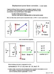
so, how to increase the power factor i.e. power factor displacement for a 900 KW load ?
 

how to increase the power factor i.e. power factor displacement for a 900 KW load
When you say 900kW , that means real power and tells nothing about power factor or reactive power.
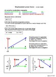
For power factor with linear loads (displacement power factor) we must know value of reactive power too.

Look these....

Disp_Power_Factor_001.jpg

Disp_Power_Factor_Correction_001.jpg


Good theory and animations about R, L and C in circuits
https://www.animations.physics.unsw.edu.au/jw/AC.html

Theory and Application of Power Factor Testing Article
https://www.electricnet.com/article.mvc/Theory-and-Application-of-Power-Factor-Testin-0001
 

so, how to increase the power factor i.e. power factor displacement for a 900 KW load ?

power factor 0.8

Calculation example.........

Power factor correction exampl_.jpg
 

can we also calculate the no. of capacitors to be used for this purpose & also their respective power handling capabilities & also their capacitance ?
 

Status
Not open for further replies.

Part and Inventory Search

Welcome to EDABoard.com

Sponsor

Back
Top