Continue to Site

Welcome to EDAboard.com

Welcome to our site! EDAboard.com is an international Electronics Discussion Forum focused on EDA software, circuits, schematics, books, theory, papers, asic, pld, 8051, DSP, Network, RF, Analog Design, PCB, Service Manuals... and a whole lot more! To participate you need to register. Registration is free. Click here to register now.

What does "100 Ohm differential" mean?

Status
Not open for further replies.

bobsun

Full Member level 2
Joined
Mar 5, 2011
Messages
120
Helped
0
Reputation
0
Reaction score
0
Trophy points
1,296
Activity points
2,239
Hello,

I would like to ask a question on impedance.

89_1300639389.png


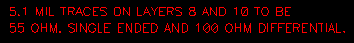
I found the following note on a PCB manufacturing file as shown in the attached picture, and reads
"5.1 mil TRACES ON LAYERS S AND 10 TO BE 55 OHM. SINGLE ended AND 100 OHM DIFFERENIIAL."

My question is:
Since it is already said to be single-ended, which means the board doesn't use differential signaling; then why there is still "100 Ohm differential" requirement? What does it refer to?


Bob
 

Attachments

  • differential.png
    differential.png
    1.3 KB · Views: 160
Last edited:

Since it is already said to be single-ended, which means the board doesn't use differential signaling
It's only said, that the single ended trace impedance should be 55 ohm. Apparently differential signaling is intended.
 
  • Like
Reactions: bobsun

    bobsun

    Points: 2
    Helpful Answer Positive Rating
Dear FvM,

I heard that German language is very precise, is it from German that your perhaps borrowed the habit of an additional comma after "It's only said" for some grammatical purposes?

And could you parse "5.1 mil TRACES ON LAYERS S AND 10 TO BE 55 OHM. SINGLE ended AND 100 OHM DIFFERENIIAL." for me? It appears to me too elliptical and I could not get its intent.


Bob
 

It would be better to know which trace layout is described here. A differential transmission line will allow to measure three different impedances.
- single ended impedance of one trace with the other connected to ground
- single ended impedance of both traces connected together, usually referred as common mode impedance of a differential pair
- differential impedance

You see, that it can be meaningful to specify single ended and differential impedance for the same differential transmission line. By changing the trace width and separation, both values are modified in a different way.
 
The numbers seem slightly off, but I'm not entirely sure of the exact implementation, so they may be fine. That being said, the measurements can both be done. Measuring from each signal conductor to ground (single-ended), you should get a 55 ohms transmission line impedance. Measuring between the two conductors, disregarding the common ground (differential), you should get 100 ohms of transmission line impedance.
 
  • Like
Reactions: bobsun

    bobsun

    Points: 2
    Helpful Answer Positive Rating
- single ended impedance of both traces connected together, usually referred as common mode impedance of a differential pair

I could not get this ... could you explain better what would be the purpose of this measurement.

As far as i understand that. Single Endend impedance is assuming the impedance a driver would see from its output to the ground, and differential impedance would be the impedance assuming the line as a load between both differential ends of a single driver, so the ground is usually used just to creat a reference fro the circuit, but it is no involved on the path (on the vision of the differential driver). Question, assuming all signals on the same frequency (and a low one), can we assume that the ground impedance is 5Ohms?

Thank you!
 
  • Like
Reactions: bobsun

    bobsun

    Points: 2
    Helpful Answer Positive Rating
The first point is to realize, that a differential pair actually has a common mode impedance. It plays a role for the transmission of (unwanted) common mode interferences. Also some differential standards, e.g. USB uses single ended signalling as part of the protocol, and thus specify a common mode impedance in addition to the differential value.

Imagine a differential pair made of two individually screened 50 ohm cables. (Not reasonable in general, but sometimes used for test and measurement purposes). It has a common mode impedance of 25 ohm and and a differential impedance of 100 ohm. If the traces are coupled, keeping the 100 ohm differential impedance, the common mode impedance will be increased.
 
Hmm ok i got. But this behavior of a protocol (like USB) using 2 lines as differential and sometime as single-end is new to me. I never heared of a USB working as single-ended, just differential. I shoud try making a USB IP core someday to understand that better. Any way, now i see what you meant.

thank you
 
  • Like
Reactions: bobsun

    bobsun

    Points: 2
    Helpful Answer Positive Rating
Dear FvM,

I have confirmed that differential refers to differential signal transmission, used on DDR2 interface for crucial clock signals.

Bob

---------- Post added at 09:53 ---------- Previous post was at 09:51 ----------

Dear enjunear,

This makes sense, and agrees with formulas I have seen (Z(diff) ~= 2Z0).

Thanks very much.

Bob
 

Status
Not open for further replies.

Part and Inventory Search

Welcome to EDABoard.com

Sponsor

Back
Top