asimkumar
Member level 4
- Joined
- Jan 1, 2011
- Messages
- 78
- Helped
- 8
- Reputation
- 16
- Reaction score
- 7
- Trophy points
- 1,288
- Location
- Chandigarh, India
- Activity points
- 1,756
Follow along with the video below to see how to install our site as a web app on your home screen.
Note: This feature may not be available in some browsers.
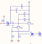
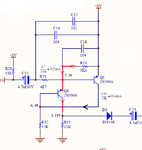
C16,17,18 are to tailor the frequency response - reduce the higher frequencies.
Frank
can u give me some links about common B design guidecommon B amplifier.
can u give me some links about common B design guide
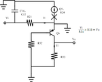
 I1 is fixed by 0.8V and R24. so we can call it a current source. the current is flow into Q6 to provide Ie and Ic.
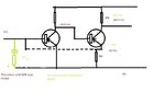
It depends how you look at it. If you change the picture slightly as below, then it looks like a common base circuit because the input is to Q6's emitter and the output is from Q6's collector.I redrew the circuit to make the emitters go "downwards" :-, can't see any common base amplifier or even any current source.
Frank
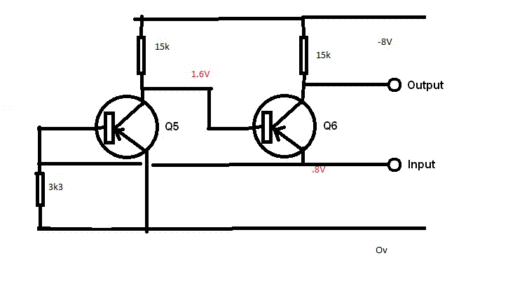


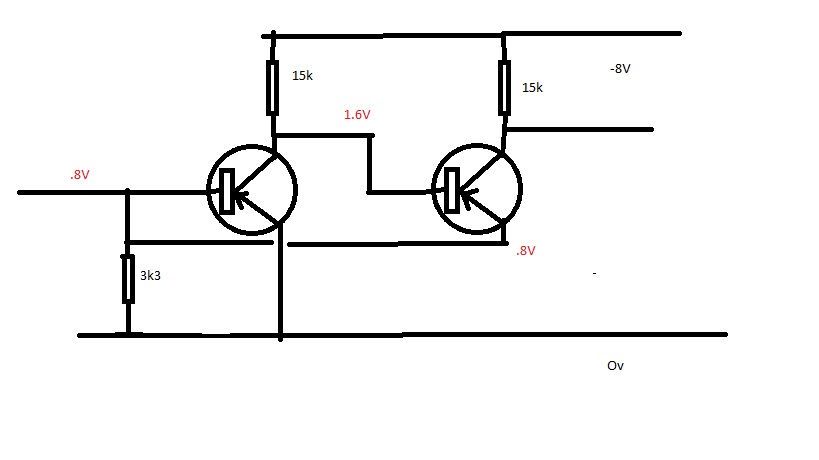
Yes, exactly - Vp is held constant. That is the voltage on the emitter, not the voltage on the base.can see from the figure Vo is amplify,and Vp is held constant.