davenn
Advanced Member level 3
- Joined
- Jul 1, 2009
- Messages
- 841
- Helped
- 192
- Reputation
- 384
- Reaction score
- 163
- Trophy points
- 1,323
- Location
- Sydney, Australia
- Activity points
- 6,382
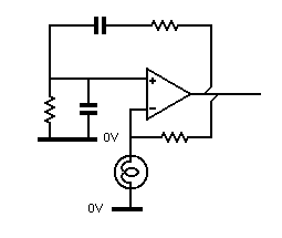
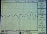
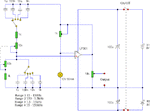
Wien Bridge Osc no go
Ok, am about to give up and start doubting my 40+ yrs of electronics experience
I cant make a simple Wien bridge Osc work
**broken link removed**
the cct looks ok when compared to various appln notes from places like Texas Inst. etc
for simplicity I have just used the pair of 100nF caps so as to leave out the complication of band switching etc
OK just for the record....
DC voltage readings around the LF351
PIN --- Voltage
1 ------- -9.28V
2 ------- 0V
3 ------- 0V
4 ------- -9.45V
5 ------- -9.25V
6 ------- -7.2V
7 ------- +9.46V
8 ------- 0V
Attachments
Last edited:
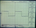
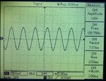
") the osc isnt with me at the moment
the osc isnt with me at the moment