gbugh
Member level 5

- Joined
- Mar 15, 2013
- Messages
- 81
- Helped
- 1
- Reputation
- 2
- Reaction score
- 1
- Trophy points
- 1,288
- Location
- Fort Worth, Texas
- Activity points
- 2,234
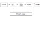
I'm trying to figure out a good AGC circuit for use with the Weaver method of SSB reception. I don't want the out of band signals affecting the AGC setting. I started thinking that if I try to use the initial RF detector's I and Q to drive the AGC then which polarity of I and which polarity of Q that I choose might affect AGC. I'm thinking I have to be careful not to let an USB signal affect AGC when I'm going to select LSB to listen to. I'm trying to visualize it all and need help.
Is it correct that if I tune a Weaver receiver and select LSB then the Weaver receiver won't be tuned to the same frequency as if I had a non-Weaver receiver tuned to LSB? I mean, because the Weaver receiver will be right in the middle of the audio instead of the audio to 1 side of the tuned frequency? Or does the RF initial detector's I and Q still shift the signal over to 1 side or the other of the selected frequency before it goes to the lower frequency Weaver stage?
While trying to figure that out I got confused because, with a Weaver receiver, I really have 4 options, not just LSB and USB. I mean, I have an initial RF detector's I and Q that can spin clockwise or counter-clockwise but then I also have the Weaver frequency I and Q that can also spin clockwise or counter-clockwise.
What happens if I spin the first set of I and Q one way while spinning the Weaver frequency I and Q the other way?
Do I have no other option but to first select my polarities of each set of I and Q to insure the AGC is not affected by a signal in the wrong sideband?
Must I really just use the final audio level out of the Weaver stage to feed the AGC circuit or is there somewhere upstream I can still pick off to drive AGC without letting the wrong sideband affect AGC?
I thought about having a separate AM detector drive AGC but that would also let too much stuff affect the AGC level when it would not necessarily be in the final band of interest.
Thanks if anyone can help,
George
73 de AF5IE

