Continue to Site

Welcome to EDAboard.com

Welcome to our site! EDAboard.com is an international Electronics Discussion Forum focused on EDA software, circuits, schematics, books, theory, papers, asic, pld, 8051, DSP, Network, RF, Analog Design, PCB, Service Manuals... and a whole lot more! To participate you need to register. Registration is free. Click here to register now.

WDT problem in Hi-Tech C Project

Status
Not open for further replies.
Joined
Dec 4, 2012
Messages
4,280
Helped
822
Reputation
1,654
Reaction score
791
Trophy points
1,393
Location
Bangalore, India
Activity points
0
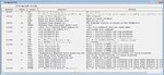
I have disabled WDT in my Project. See attached files. See Proteus simulation log. I am testing the code on both hardware and Proteus and both has the same problem. Processor is resetting and dues to that display blinks. Proteus log tells Processor is resetting due to WDT. I have used Hi-Tech C's delay function. Is it causing the problem? If I try the same code in mikroC it works fine.
 

Attachments

  • pic18f458_20 MHz 4-bit lcd.rar
    7.5 KB · Views: 69

In ISIS open the PIC properties. In the "Advanced Properties" field choose 'Enable Watchdog timer?' and set it to 'NO' instead of 'Default'. This will totally disable the WDT regardless of the Configuration Bits in your code. You should check the code though because the 'Default' value actually reads the configuration bit of the WDT in your code, which means, your code is not disabling the WDT.
 

Then probably you've made a mistake somewhere else in your code. Are you using MPLAB to compile the code? If so, check that in the menu config > Configuration bits the Configuration bits set in code checkbox is checked. If not, check it or set your preferences to your needs. Also, if possible, make a simple PIC test program to check that your PIC is running (make a simple LED test program).
It would be nice if you could post even a small part of your code (main and pre-main global code) to check for any misconfiguration you may have done. The hex file only is not enough to determine the mistake.
 

This is the code of main.c


Code C - [expand]
1
2
3
4
5
6
7
8
9
10
11
12
13
14
15
16
17
18
19
20
21
22
23
24
25
26
27
28
29
30
31
32
33
34
35
36
37
38
39
40
41
42
43
44
45
46
47
48
49
50
51
52
53
54
55
56
57
#include <htc.h>
 
 
//Define CPU Frequency
//This must be defined, if __delay_ms() or
//__delay_us() functions are used in the code
#define _XTAL_FREQ   20000000
 
// Configuration word for PIC16F877
__CONFIG( FOSC_HS & WDTE_OFF & PWRTE_OFF & CP_OFF & BOREN_OFF
    & LVP_OFF & CPD_OFF & DEBUG_OFF);
 
//Define Pins
#define LCD_RS PORTBbits.RB1             // RS pin for LCD
#define LCD_EN PORTBbits.RB2             // Enable pin for LCD
#define LCD_D4 PORTBbits.RB4             // Data bus bit 4
#define LCD_D5 PORTBbits.RB5             // Data bus bit 5
#define LCD_D6 PORTBbits.RB6             // Data bus bit 6
#define LCD_D7 PORTBbits.RB7             // Data bus bit 7
 
//Define Pins direction registrers
#define LCD_RS_Direction TRISBbits.TRISB1
#define LCD_EN_Direction TRISBbits.TRISB2
#define LCD_D4_Direction TRISBbits.TRISB4
#define LCD_D5_Direction TRISBbits.TRISB5
#define LCD_D6_Direction TRISBbits.TRISB6
#define LCD_D7_Direction TRISBbits.TRISB7
 
#define LCD_PORT PORTB
 
#include "lcd.h"
 
int main(){
 
    TRISB = 0x00;
    PORTB = 0x00;
    
    LCD_Init();
    LCD_Cmd(_LCD_CLEAR);
    LCD_Cmd(_LCD_CURSOR_OFF);
    LCD_Cmd(_LCD_FIRST_ROW);
    LCD_Out(1,1,"LCD 4-bit Library");
    LCD_Cmd(_LCD_SECOND_ROW);
    LCD_Out(2,1,"Hi-Tech C");
    LCD_Cmd(_LCD_THIRD_ROW);
    LCD_Out(3,1,"by");
    LCD_Cmd(_LCD_FOURTH_ROW);
    LCD_Out(4,1,"Jayanth D");
    LCD_Out(2,12,"OK");
    LCD_Cmd(_LCD_BLINK_CURSOR_ON);
    
    while(1){
            ;
    }
 
    return (0);
}


See attached image. For PIC16F, I use the above code and the image shown. If I use PIC18F, I Comment out the Config bits in Code and then in the image I uncheck the "Config Bits set in Code" Checkbox.

90677d1367892856-configpic18f.jpg
 

Attachments

  • configpic18f.jpg
    configpic18f.jpg
    256.7 KB · Views: 110

Very strange... the code is OK and the configuration bits window looks like WDT is disabled; it should have worked just fine. Have you looked in the manual fort other special function registers that need to be properly configured ? I see in the configuration bits window, the WDT disabled status also reports a "control is placed on the SWDTEN bit", do you know what this means and if it has anything to do with it?
 

I haven't had time to go through the code yet but if the real hardware watchdog is causing a reset, the most obvious place for it is the while(1); loop. Try inserting an asm statement inside the loop to reset the timer "clrwdt".

Brian.
 

You're right, Brian, this would reset the WDT. But I've read the code and looked at the settings, and it looks like the WDT should have never started counting in first place as long as the WDT settings are set to disable it. Now, either jayanth is re-enabling it somehow later, or the code is not properly compiled, or there are other registers to be properly configured.
 

@T3STY

Here is my full Code. I have not used WDT anywhere in the code. I am using _delay_ms() and _delay_us() library function. If they enable WDT then I don't know.

https://www.edaboard.com/threads/287832/

- - - Updated - - -

@betwixt

I haven't done inline asm in XC8 Compiler yet. Can you show an example about how to do inline asm in XC8?

I tried this but it gives error.


Code ASM - [expand]
1
2
3
_asm
      clrwdt                
_endasm


Edit:

I found it. I have to do like this.


Code ASM - [expand]
1
asm("clrwdt");

 
Last edited:

@T3STY

Here is my full Code. I have not used WDT anywhere in the code. I am using _delay_ms() and _delay_us() library function. If they enable WDT then I don't know.
No, those functions actually work with assembler instructions counting until they reach the end (either 0 for DECFSZ or the specified number for INCFSZ), they are made on purpose to be code latency rather than a physical timer counting.
As I read your code it still looks OK, I couldn't find any line that re-enables the WDT. May I suppose a compiler error? I really don't know why the WDT is still enabled, it shouldn't be. I'll make a few tests in MPLAB and ISIS as soon as possible.

Oh, now that I remember a bug of MPLAB, if you start a project with a PIC and then change the PIC settings and the configuration bits, they actually don't change at all. a few days ago I was forced to create a new MPLAB project because the compiler was still using the old PIC settings. Maybe you're having the same issue too?
 

Status
Not open for further replies.

Similar threads

Part and Inventory Search

Welcome to EDABoard.com

Sponsor

Back
Top