Continue to Site

Welcome to EDAboard.com

Welcome to our site! EDAboard.com is an international Electronics Discussion Forum focused on EDA software, circuits, schematics, books, theory, papers, asic, pld, 8051, DSP, Network, RF, Analog Design, PCB, Service Manuals... and a whole lot more! To participate you need to register. Registration is free. Click here to register now.

waveport size for Grounded-CPW simulation help!!!

Status
Not open for further replies.

nhomuathu_hanoi

Member level 5
Joined
Apr 26, 2007
Messages
94
Helped
24
Reputation
48
Reaction score
13
Trophy points
1,288
Location
Hometown
Activity points
1,790
hi everybody,

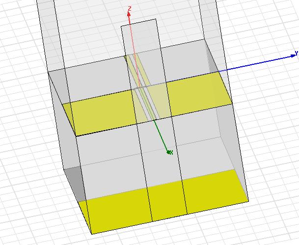
I'm trying with grounded Coplanar waveguide simulation in HFSS.

I use GaAs substrate with related permitivity of 12.9, 680um of thickness. And parameters for G-CPW are S = 30 um, G = 22 um, that corresponding to 50 Ohm characteristic impedance.
I sized the waveport with 3*(S+2G), 4*h for the port width and height, respectively. But I haven't successed in port mode.
Could you tell me what the size should be?

Thank you!
 

please upload the picture of your waveport.
 

hi Burton,
First, thank you for your consideration.
In the following picture, the port_height is 2*h and it leads to a wrong field distribution.
The same results were obtained when I increased continuously the port height upto 4*h, even resized the port_width.
Could you comment some thing?


There are a number of considerations: Nodal or driven solutions. Wave or lumped ports. Look at the impedance calculation section in on-line help for additional guidance on CPW lines. A grounded CPW is mode rich and there are numerous ways to go astray. Examine the port fields to make sure you are exciting the transmission line in the manner you desire.

If you are using a grounded CPW you probably also need to pay attention to via stiching and placement. This will be an issue as you get into the microwave bands.

I would also compare the results with an independent calculator like Polar's Si9000 just to make sure I was not wandering around in the weeds. I am not suggesting that Si9000 is a better tool. If you look around on the web you can find a number of free impedance calculators, some with grounded CPW lines.

By the way, port size matters too. Bigger ports sometimes help.
 
hunerdspoke@
Thank you for your time!
Azulykit@
Thank so much for your useful comment and suggestion. I also use another independent tool to calculate the transmission line impedance but never thought about comparing its result to port characteristic impedance.
The Most likely port field distribution and a matched characteristic impedance will be acceptable, by the way that I understand.
 

I also encounter the same problem with you recently.

Have you solved this probelm now?

If so, please give me some suggestion. Thanks very much.
 

Status
Not open for further replies.

Part and Inventory Search

Welcome to EDABoard.com

Sponsor

Back
Top