Continue to Site

Welcome to EDAboard.com

Welcome to our site! EDAboard.com is an international Electronics Discussion Forum focused on EDA software, circuits, schematics, books, theory, papers, asic, pld, 8051, DSP, Network, RF, Analog Design, PCB, Service Manuals... and a whole lot more! To participate you need to register. Registration is free. Click here to register now.

Wave Port outside the calculation domain in CST

Status
Not open for further replies.

rebocato

Newbie
Joined
May 3, 2015
Messages
3
Helped
0
Reputation
0
Reaction score
0
Trophy points
1
Activity points
28
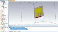
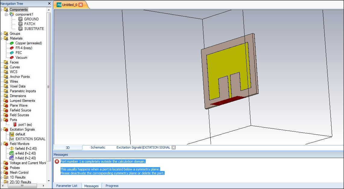
Hi everyone, i been trying to design and simulate a rectangular patch w/microstrip coupling antenna @ 2.4 GHz W/FR4 but i can't get it, because at the time to simulate the patch in CST i've this error:
"Port number 1 is completely outside the calculation domain.
This usually happens when a port is located below a symmetry plane.
Please deactivate the corresponding symmetry plane or delete the port."

I made changes again & again but i get nothing (deleting port, add new port, start new project, change lenght of microstrip), any one could help me how to solve that error??


Really thanks for your attention.
 

Looks like you've got your symmetry planes (Boundaries --> Symmetry plane) set up wrong. Seems to me that your port does not have a symmetry . To solve that, remove symmetry plane where there is no symmetry in your structure. You should only have one symmetry plane in the structure you posted.

Hope that was clear, if you need further clarification you could upload screen shots of said symmetry plane configuration and the orientation (x,y,z) of your structure.
 
No problem, i've changed my boundary conditions in symetry planes two simulations ago, i used electric field for XZ plane and in the last try i used magnetic field to YZ plane and now the error it's gone, i don't understad at all why, but it works.
 

Attachments

  • PATCH.zip
    18.9 KB · Views: 119

I did it, I've been changed boundary conditions and it works but is certainly strange because two shots ago i tried with electric and magnetic field in the XZ plane and error still there, but now it's gone ahaaa, one more thing!! i used the macro (calculation extension port coefficient). Really Thanks.
 

Good on you! If you have a look at your structure, you really only have symmetry in the YZ plane (which is what you fixed it to). Setting symmetry for XZ plane gives you the error as you mentioned in your post, because your port is not in the calculation domain. When you define one symmetry plane, your structure basically cuts in half for that plane (solver only calculates half of your structure and assumes the other side of your symmetry is identical).

When you define XZ symmetry plane, you have your port on one end, but not the other. Therefore it is not symmetrical.
Another thing to note: Apart from the waveguide port defined, there really isn't symmetry in the XZ plane due to the microstrip feed line. I added this comment because if you happen to feed your patch with a coax in the center of patch, but do not have symmetry in the plane you are defining, the error message will not show and you will definitely get unexpected results. Worse yet, receiving wrong results thinking they are right!

Hope that helps and all the best!
 

Status
Not open for further replies.

Similar threads

Part and Inventory Search

Welcome to EDABoard.com

Sponsor

Back
Top