Continue to Site

Welcome to EDAboard.com

Welcome to our site! EDAboard.com is an international Electronics Discussion Forum focused on EDA software, circuits, schematics, books, theory, papers, asic, pld, 8051, DSP, Network, RF, Analog Design, PCB, Service Manuals... and a whole lot more! To participate you need to register. Registration is free. Click here to register now.

[PIC] Watchdog timer don't work on PIC18f67J94

Status
Not open for further replies.

brankobr

Newbie level 4
Joined
Dec 23, 2021
Messages
6
Helped
0
Reputation
0
Reaction score
0
Trophy points
1
Activity points
35
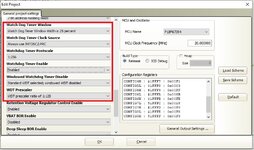
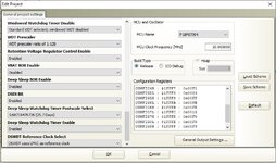
I configured PIC18F67J94-I/PT as in pictures in attachment, nowhere in code put CLRWDT instruction, and I expect that PIC reset after some time, but reset never happens.
Can someone help me, please?
 

Attachments

  • wdt3.jpg
    wdt3.jpg
    138.6 KB · Views: 112
  • wdt1.png
    wdt1.png
    38.8 KB · Views: 124
  • wdt2.jpg
    wdt2.jpg
    138.9 KB · Views: 107
  • wdt4.jpg
    wdt4.jpg
    130.6 KB · Views: 110

Hi,

How do you know RESET never happens?
What is your exact test mode, HW, SW, measurement devices...?

Klaus
 

Hi,

How do you know RESET never happens?
What is your exact test mode, HW, SW, measurement devices...?

Klaus
I have GLCD display that changes view, and buzzer that makes sound on reset, also relays that turns off. So I'm sure that RESET never happens because device is working without any change.
 

Hi,

It's very unlikely that the watchdog system in a PIC does not work.
Thus I see just some possible reasons for your problem
* the watchdog setup is not properly programmed into the circuit
* wrong code
* wrong test method

Your given informations are too vague for us to validate.

If you don't want to show us your code, then I recommend to use just a minimal code containing:
* port setup
* testpin = output, Low
* wait 10ms
* testpin = output, High
* infinite loop

Then use a digital scope at the testpin with proper trigger detection.

Calculate the expected watchdog timeout.

Klaus
Thanks a lot! I will try this!
It's not problem to show you code if you can help me.
 

What language is your code written in?
Unless you are coding in pure assembly language it is quite likely that the compiler has inserted watchdog resets in the code by itself or it has included a library that incorporates them.

Brian.
 

What language is your code written in?
Unless you are coding in pure assembly language it is quite likely that the compiler has inserted watchdog resets in the code by itself or it has included a library that incorporates them.

Brian.
I use mikroC pro for PIC compiler, C language.
I also think that problem may be in compiler.
Do you have idea how to solve this.
 

The usual way to trigger a watchdog reset is to disable all interrupts and perform an endless loop e.g.
Code:
INTCON.GIE = 0;
while (1);
 

The usual way to trigger a watchdog reset is to disable all interrupts and perform an endless loop e.g. while (1);
If timer 1, and timer 2 interrupts are enabled, can WDT reset PIC? I think that it should.
 

Hi,

WDT does not depend on timer and interrupts.

It just depends on WDT setup and WDT RESET...(at least I can´t remember anything else)

****
Are you aware that a "RESET" may be a very short event? It maybe just takes 10us (depending on your code). So it surely is possible that you don´t even see the tinyiest flicker on an GLCD. Thus I don´t think a GLCD is a proper test method.

But as long as you don´t give informations like schematic, code, clear test methods, feedback on recommended test routines.... it´s impossible for me to further assist you.

***
If you "think" it´s a compiler problem... then have a look at the compiler output files. I expect a file that contains the assembler code. Please understand, we don´t have this file .... so you have to check it on your own.

Klaus
 

If timer 1, and timer 2 interrupts are enabled, can WDT reset PIC? I think that it should.
Yes, if you are sure that the interrupt functions don't indirectly perform a WDT clear. mikroC documentation doesn't seem to tell anything about internal CLRWDT usage, but it can be expected at least for built-in software delay instructions. Inspecting the generated code maybe the only way to find out.
--- Updated ---

You didn't tell much about your code layout. In which state of code execution are you expecting the watchdog reset to occur?
 
Last edited:

I found solution for this problem. Compiler mikroC pro for PIC, has a bug, and when you select in the wizard Watchdog timer enabled, it writes wrong value in .cfg file. I have edited values in .cfg file by myself, and now WDT works as expected.
 

Status
Not open for further replies.

Similar threads

Part and Inventory Search

Welcome to EDABoard.com

Sponsor

Back
Top