Continue to Site

Welcome to EDAboard.com

Welcome to our site! EDAboard.com is an international Electronics Discussion Forum focused on EDA software, circuits, schematics, books, theory, papers, asic, pld, 8051, DSP, Network, RF, Analog Design, PCB, Service Manuals... and a whole lot more! To participate you need to register. Registration is free. Click here to register now.

Want to know operation of this Schematic

Status
Not open for further replies.
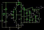
Well ofcourse threshold voltage would be 24VDC, any how this circuit is operating on 24VDC voltage, so i need to mitigate those unsafe failure? is there any way by mitigate those unsafe failure by changing the values of C1,C2,R7 and R8 or placing those components parallely like instead of just C1 place 2 Caps same as for R7 and R8.

Give your advice on this.
 

Well ofcourse threshold voltage would be 24VDC

By threshold I guess I meant the threshold for the relay to operate.

The failure modes would not be a hazard if the relay would stop operating. The problem is that you have partial operation, with unknown results.

It now appears that you must choose between two conflicting goals:

(1) to get the volt level **well above** the relay's threshold, so that operation will continue even if the power supply goes down a few volts,
or
(2) to get the volt level **barely** above the threshold so that it will fall below that threshold if a component fails.

Issues like this make a project complicated. Seems like every project has one of these 'gotchas' hidden somewhere.

Your team (or the boss) must decide whether it's better for the circuit to shut down if a component fails, or whether it should have redundancy built in.

One idea: it may work to install a smoothing capacitor on the right half of the circuit.

Or change the value of the zener diode DZ3. That determines the threshold for the op amp input. The op amp acts as a comparator with snap action.

is there any way by mitigate those unsafe failure by changing the values of C1,C2,R7 and R8

Only if you are lucky. Experimentation is the way to find out. Also try adding this or that component in different positions.

or placing those components parallely like instead of just C1 place 2 Caps same as for R7 and R8.

I suppose you mean to install a second capacitor to compensate if one fails? The only way to find out is to try different things.

You can build in a certain amount of redundancy. This will let operation continue if a component fails. But then your redundant items must pass a failure analysis too.
 

I am still not getting how i can identify the threshold level of relay? how can i measure the threshold level of relay?

I cant understand your 1 and 2 points which you have mentioned above, can you elaborate on that?

Yes you are right every project has some gotchas, in this project i require circuit to be shut down if any component fails (what are the necesssary changes require to mitigate those false triggering, if you could modify in falstad circuit)

Where exactly i have to place smoothing capacitor? what it can do ? it can resolve false triggering?

how can i build redundancy in circuit? what component i have to change?
 

Brad,

I had played with circuit and i have resolved almost every failure which was happening before, go through the attached falstad scipt file, kindly review it and give your feedback.

but still one problem is , any of this diode D1,D1',D2 and D2' is short at that time relay chattering is happening which is again a unsafe failure, i tried many logics but it wont solve this problem, need your technical guidance on this.
 

Attachments

  • final.txt
    3.7 KB · Views: 49

I am still not getting how i can identify the threshold level of relay? how can i measure the threshold level of relay?

1. Run current through the relay. Start low and increase. When the relay closes, record the voltage across it and current through it.

2. Reduce current gradually until the relay opens. Record the voltage and current.

You have just measured the relay's operating thresholds.

These figures are a chief concern in this project.

I cant understand your 1 and 2 points which you have mentioned above, can you elaborate on that?

To obtain reliable turn-on, you want to make your control circuit apply power well above the relay's operating threshold. That has been the goal so far.

However after doing failure analysis, you find the power will be a little above and a little below that threshold, in the event that certain components fail.

Since you don't want partial operation, it creates a different goal. Now you may need to alter your threshold for on and off.

At the same time you don't want the relay to shut off if the supply voltage drops a volt or two.

These goals are not easy to satisfy.

in this project i require circuit to be shut down if any component fails (what are the necesssary changes require to mitigate those false triggering, if you could modify in falstad circuit)

I think you mean if YOU could modify in the Falstad circuit.

Falstad's simulator is handy for this purpose because you can move components around, experiment with values, and see results immediately.

When we are troubleshooting, it is often necessary for us to have to try everything under the sun.

Where exactly i have to place smoothing capacitor? what it can do ? it can resolve false triggering?

Try 22 uF, connected to the top of D1 and bottom of D2. It may not cure all the failure conditions, but it may cure one or two.

how can i build redundancy in circuit? what component i have to change?

Just try anything and everything that could make a difference.

Falstad's shows the relay contact moving up and down in one or 2 failure conditions. This will make it easy to see what happens when you change something around.

- - - Updated - - -

Brad,

I had played with circuit and i have resolved almost every failure which was happening before, go through the attached falstad scipt file, kindly review it and give your feedback.

but still one problem is , any of this diode D1,D1',D2 and D2' is short at that time relay chattering is happening which is again a unsafe failure, i tried many logics but it wont solve this problem, need your technical guidance on this.

I'm watching your revised circuit operate.

You added duplicate components. It is one way to create redundancy and it can work in some situations.

However with the additional components, it reduces impedance between the incoming supply and the right half of the circuit. The relay closes for a moment when power is first hooked up. You must find out if this is permitted in UL specs.

It could be preferable to make each component essential, with no redundancy permitted. Example, R7 and D4 are in parallel. They appear to do a similar job. Is there a time when one is needed and the other is not? I have not figured that out.

And, what if each diode's direction (D4, D5) was wrong? What if we reverse the directions? Would that cure any of the failure conditions? Could a mistake have been made in the original drawing? Things like that are known to happen.
 

1. Run current through the relay. Start low and increase. When the relay closes, record the voltage across it and current through it.

2. Reduce current gradually until the relay opens. Record the voltage and current.

You have just measured the relay's operating thresholds.

These figures are a chief concern in this project.

Yes sure i will test it and find out threshold voltage


To obtain reliable turn-on, you want to make your control circuit apply power well above the relay's operating threshold. That has been the goal so far.

However after doing failure analysis, you find the power will be a little above and a little below that threshold, in the event that certain components fail.

Since you don't want partial operation, it creates a different goal. Now you may need to alter your threshold for on and off.

At the same time you don't want the relay to shut off if the supply voltage drops a volt or two.

These goals are not easy to satisfy.

Well i would like to operate the relay 21.6VDC to 26VDC, but relay should not chattering(toggle or blink) because its a unsafe failure, i dont mind if relay gets open or disconnected if any of the component gets short or open


I think you mean if YOU could modify in the Falstad circuit.

Falstad's simulator is handy for this purpose because you can move components around, experiment with values, and see results immediately.

When we are troubleshooting, it is often necessary for us to have to try everything under the sun.

you can guide me i wil do require changes from my side


Try 22 uF, connected to the top of D1 and bottom of D2. It may not cure all the failure conditions, but it may cure one or two.

Please have a look on attached picture and let me know if this connection is okay or not?


Just try anything and everything that could make a difference.

Falstad's shows the relay contact moving up and down in one or 2 failure conditions. This will make it easy to see what happens when you change something around.

- - - Updated - - -


I'm watching your revised circuit operate.

You added duplicate components. It is one way to create redundancy and it can work in some situations.

However with the additional components, it reduces impedance between the incoming supply and the right half of the circuit. The relay closes for a moment when power is first hooked up. You must find out if this is permitted in UL specs.

It could be preferable to make each component essential, with no redundancy permitted. Example, R7 and D4 are in parallel. They appear to do a similar job. Is there a time when one is needed and the other is not? I have not figured that out.

And, what if each diode's direction (D4, D5) was wrong? What if we reverse the directions? Would that cure any of the failure conditions? Could a mistake have been made in the original drawing? Things like that are known to happen.

Yes you are right i have added duplicate components, so if any of the components gets open or short it should not create chattering in the relay which is unsafe failure.

If we are not providing a clock relay should not connect, and its okay as per UL

The purpose of risk analysis is to check the performance of the circuit if any components gets open or short.

Yes for the direction of D5 and D6 i need to check in the UL wheather we should consider such condition or not?

Most of the unsafe failures (chattering) has been resolved by duplicating the components BUT i am unable to find a solution for one condition which is if either D1 short or D2 short still relay chattering is happening, could you help me to resolve this problem? give me some idea or technique to resolve this failure
 

Attachments

  • Smoothing capacitor update picture.jpg
    Smoothing capacitor update picture.jpg
    209.7 KB · Views: 59

Please have a look on attached picture and let me know if this connection is okay or not?

As I look I realize the smoothing capacitor can be C3 (22uF). Try this: Reduce resistor R9 to 10 ohms. (Or possibly remove it and replace it with a wire.)

Yes for the direction of D5 and D6 i need to check in the UL wheather we should consider such condition or not?

D4 and D5? Notice when R7 and R8 are very low, the diodes D4 and D5 become of no purpose. This could start to lose sight of the original purpose of the circuit, namely to create a failsafe operation of the relay.

With all these components getting multiplied, I have a suspicion the boss will ask, 'Can't we make this with fewer components?'
 

Yes you are right post 106 do not serve the purpose of our goal.

recently i came to know from UL , when any of the component fail relay should deenergize otherwise unwanted connection can turn on the boiler which is not acceptable. so we have to focus in our original circuit.

Do you have any idea how we can modify our original circuit so it can operate in above mentiond condition?, relay should turn off when any component fails (means open or short)

I have tried to reduce the value of R9 from 330 to 10 ohms but its not solving the problem.
 

Approaches that should be tried...

* Reduce current flow so it is just over the threshold to operate the relay.

* Reduce C1 and C2. Increase R7 & R8.

* Increase the value of zener ZD3.

* Spend a lot of time watching the animated action of the circuit. Move a component to create one of the unsolved failure conditions. Picture what other thing you must do to prevent the relay from toggling. Use your imagination. Think how current might be rerouted, or diverted, or obstructed, or split, or reduced, to solve a failure condition.

* Find out whether the failure analysis recognizes that a relay has a certain amount of hysteresis. It may chatter at 30 Hz, but it won't chatter at 1 kHz.

----------------------

You have reached the difficult stage in the development of a project. This failure analysis has thrown a monkey wrench into the process.

Do not limit yourself to my above suggestions. Draw on all ideas.

You must rework the circuit so it gets past the failure analysis. Do not expect to do it in one day.

Although this schematic may appear in a patent document, that fact does not guarantee that it will satisfy all requirements.

You may need to contact the person who holds the patent. He may or may not be interested in helping you. It probably will depend on what you offer him or her. Or what your persuasive salesman can offer. Or what your persuasive boss can offer.

If you cannot use your ingenuity to get through the failure analysis, then you may have to trash the circuit. It happens to many design teams.
 

Yes i will those approches
One thing i want to clear from you that do i need to freeze the value of R9 from 330 to 10 ohms? or should i move forward with old circuit which has 330 ohms R9.
how ZD3 (if i increase the value)can helps to mitigate the unsafe failures?
As per your knowledge which frequency i have to freeze to operate the circuit, because i cant play by changing a multiple value simultaneously.
Yes you are right i am in very difficult stage, and i am stretching my hands to other resources as well.
Yes i understand that patent is reference design.
Have a look on attached falstad script i have changed the value of R and C in such a way that its operate on 24VDC only, and in simulator i came to know that 13.1 ma current require to turn on the relay in simulator (in practical this value might get change).
I guess practically you dont get both facility 1) voltage tolerence in supply 20.4VDC to 26.4VDC 2) relay should off when any component fails, whats your thought on this? correct me if i am wrong
As per your suggestion i have also tried to change the value of DZ3 but there is no effect in relay condition if you increase or decrese
 

Attachments

  • 24VDC.txt
    3 KB · Views: 45
Last edited:

Yes i will those approches
One thing i want to clear from you that do i need to freeze the value of R9 from 330 to 10 ohms? or should i move forward with old circuit which has 330 ohms R9.

The UL alerts happen because of unstable operation of the relay.

Therefore it will help to provide the relay with a supply that does not pulsate in a failure event.

Disconnect the relay from node X. Connect it to the top of capacitor C3.

Leave R9 at 10 ohms.

My simulation shows this will cure unstable toggling of the relay in a failure event.

how ZD3 (if i increase the value)can helps to mitigate the unsafe failures?
As per your knowledge which frequency i have to freeze to operate the circuit, because i cant play by changing a multiple value simultaneously.

This comparator circuit apparently is supposed to be adjusted so op amp output goes high only at a reliable high supply level. Then the zener diode level is exceeded. The zener value should be 19V.

R13 has been too high all along. It should be 100k. This will cause the threshold of operation to depend on the zener diode value.

Have a look on attached falstad script i have changed the value of R and C in such a way that its operate on 24VDC only, and in simulator i came to know that 13.1 ma current require to turn on the relay in simulator (in practical this value might get change).

Yes, the real relay will not necessarily open and close at the simulator values.

Hence you can expect to perform further stages of troubleshooting with real hardware.

I guess practically you dont get both facility 1) voltage tolerence in supply 20.4VDC to 26.4VDC 2) relay should off when any component fails, whats your thought on this? correct me if i am wrong

Yes, this is where you must create cooperation. You want the relay board to operate at normal supply voltages.

You must find out how low the supply voltage might **normally** be expected to go (in the winter season). You must adjust the threshold of operation so normal drops in house voltage will not cause the relay board to go into failure mode.

As per your suggestion i have also tried to change the value of DZ3 but there is no effect in relay condition if you increase or decrese

See my answer above regarding the zener value.
 

Brad, have look on attached snap, i have changed the value as per your suggestion but relay is not ceonnecting at all, i have changed the following value

R9 330 ohm to 10 ohm
DZ3 16V to 19V
R13 22K to 100K
Relay connects to the the top of C3
 

Attachments

  • Modified circuit.jpg
    Modified circuit.jpg
    186.3 KB · Views: 62

Brad i have tried 18V DZ3 but still not getting proper result, relay gets toggle when any of the component open.
Please find the attached snap for your reference.
Which circuit currently you consider the 24VDC script which i have attached in Post 110 or our original circuit?
I have check both circuit where C1 and C2 are 10 uf and C1 and C2 are 68uf but i found same result relay is toggeling very badly.

New test
I have changed the values of the R and C in such a way that,it resolve some of the conditions,but i need your advice how i can resolve the other conditions which is not solved, result are as under
C1 open RL1 connects to NC (UL satisfied)
C1 short RL1 Connects to NO (UL not satisfied)
R7 open RL1 connects to NC (UL satisfied)
R7 short RL1 Connects to NO (UL not satisfied)
D4 open RL1 connects to NO (UL not satisfied)
D4 short RL1 Connects to NO (UL not satisfied)
D1 open RL1 connects to NC (UL satisfied)
D1 short RL1 Connects to NC (UL satisfied)
D2 open RL1 connects to NC (UL satisfied)
D2 short RL1 Connects to NC (UL satisfied)
C2 open RL1 connects to NC (UL satisfied)
C1 short RL1 Connects to NO (UL not satisfied)
R8 open RL1 connects to NC (UL satisfied)
R8 short RL1 Connects to NO (UL not satisfied)
D5 open RL1 connects to NO (UL not satisfied)
D5 short RL1 Connects to NO (UL not satisfied)

You can simulate your end by using23102012 circuit script file
 

Attachments

  • DZ3 18VDC.JPG
    DZ3 18VDC.JPG
    55.6 KB · Views: 61
  • 23102012 circuit.txt
    2.9 KB · Views: 54
Last edited:

Brad i have tried 18V DZ3 but still not getting proper result, relay gets toggle when any of the component open.
Please find the attached snap for your reference.
Which circuit currently you consider the 24VDC script which i have attached in Post 110 or our original circuit?
I have check both circuit where C1 and C2 are 10 uf and C1 and C2 are 68uf but i found same result relay is toggeling very badly.

New test
I have changed the values of the R and C in such a way that,it resolve some of the conditions,but i need your advice how i can resolve the other conditions which is not solved, result are as under
C1 open RL1 connects to NC (UL satisfied)
C1 short RL1 Connects to NO (UL not satisfied)
R7 open RL1 connects to NC (UL satisfied)
R7 short RL1 Connects to NO (UL not satisfied)
D4 open RL1 connects to NO (UL not satisfied)
D4 short RL1 Connects to NO (UL not satisfied)
D1 open RL1 connects to NC (UL satisfied)
D1 short RL1 Connects to NC (UL satisfied)
D2 open RL1 connects to NC (UL satisfied)
D2 short RL1 Connects to NC (UL satisfied)
C2 open RL1 connects to NC (UL satisfied)
C1 short RL1 Connects to NO (UL not satisfied)
R8 open RL1 connects to NC (UL satisfied)
R8 short RL1 Connects to NO (UL not satisfied)
D5 open RL1 connects to NO (UL not satisfied)
D5 short RL1 Connects to NO (UL not satisfied)

You can simulate your end by using23102012 circuit script file

You added a capacitor across the relay coil. Good idea. This will reduce the chattering tendency.

We can use your latest schematic.

I have tried various arrangements to create a greater voltage drop when a component fails, so that the relay coil gets insufficient current.

Sorry my latest ideas did not work (changing zener value, etc.). The aim is to provide the relay coil with just enough current (13 mA) to close the contacts. A failure of C1 or C2 still provides current over 12mA, and this causes the instability.

I have tried putting resistors inline with diodes D1 & D2. 33 or 47 ohms.

I have tried changing R6 to 10k. This cuts down current through the transistors.

There is a strange situation with op amp A2. Falstad's simulator does not explicitly show supply and ground connections. It is possible that a current path through that op amp is referenced to the left half of the circuit rather than the right half. It amounts to a few mA, but it could conceivably make a difference regarding the instability issue.

It might pay to test the circuit in a different simulation program. What simulator was used for the UL test?
 

Yes parallel capacitor can reduce the relay chattering, but i dont know which value would be suitable, how would i find the value of capacitor?
Latest means which schematic, can you define post no.?
dont be sorry its okay, yes you are right zener idea did not work,component failure also provide 12 ma or above thats why its connecting.
Resistors across parallel to D1 and D2 or in series, if in series where should i have to place a resistor top of D1 and bottom of D2 or something else?
I am not getting your point regrading A2 Op-amp, can you elaborate more on this?
I dont have any idea what simulator UL using when they are performing UL test, we generally undertake the UL test to other vendor not doing test in house.
 

Attachments

  • D1 D2 resistors.JPG
    D1 D2 resistors.JPG
    53.3 KB · Views: 59

Yes parallel capacitor can reduce the relay chattering, but i dont know which value would be suitable, how would i find the value of capacitor?

Large enough value so voltage across it doesn't vary by more than, say 10 percent.

Latest means which schematic, can you define post no.?

When so many revisions have been made, it becomes wise to put the date in the name. Such as your post #116. Seems okay to use it.

Resistors across parallel to D1 and D2 or in series, if in series where should i have to place a resistor top of D1 and bottom of D2 or something else?

They are circled in the diagram:

6689736500_1351162279.gif


Adding them does not necessary solve the problem, however.

The upper charge pump contributes 65 percent and the lower charge pump contributes 65 percent. Even if you knock out 1/2 of either one, they produce enough combined power to get the relay just barely to its threshold for turning on.

The goal is to create a greater drop in power when a component fails.

I am not getting your point regrading A2 Op-amp, can you elaborate more on this?

The two op amps should not be powered by the same supply. (The hardware should consist of two separate IC's.)

Now, since A2 is in the right half of the circuit, its power supply should come from the right half of the circuit. However I am not sure that Falstad's simulator is calculating A2's power in that manner.

I'm not sure it is a crucial difference. But we want to catch any unexpected problem, rather than have it catch us.
 

yes for the confirmation and recheck the simulation i am simulating this circuit on TINA simulator (from taxs instrument), in this simulator i am applying diffrent power supply for both op-amp A1 and A2.
Its a free tool you can also download and install it at your end.
 

Status
Not open for further replies.

Similar threads

Part and Inventory Search

Welcome to EDABoard.com

Sponsor

Back
Top