Continue to Site

Welcome to EDAboard.com

Welcome to our site! EDAboard.com is an international Electronics Discussion Forum focused on EDA software, circuits, schematics, books, theory, papers, asic, pld, 8051, DSP, Network, RF, Analog Design, PCB, Service Manuals... and a whole lot more! To participate you need to register. Registration is free. Click here to register now.

VoltMeter with Digital Display - Problem

Status
Not open for further replies.

semiconductor

Full Member level 4
Joined
Apr 4, 2003
Messages
236
Helped
4
Reputation
8
Reaction score
0
Trophy points
1,296
Activity points
2,735
7107 digital voltage meter

I've just bought Voltage and Current Meter with Digital Display. I found on the PCB 3 main ICs:
- TL431
- CD4069 (inverter)
- ICL7107

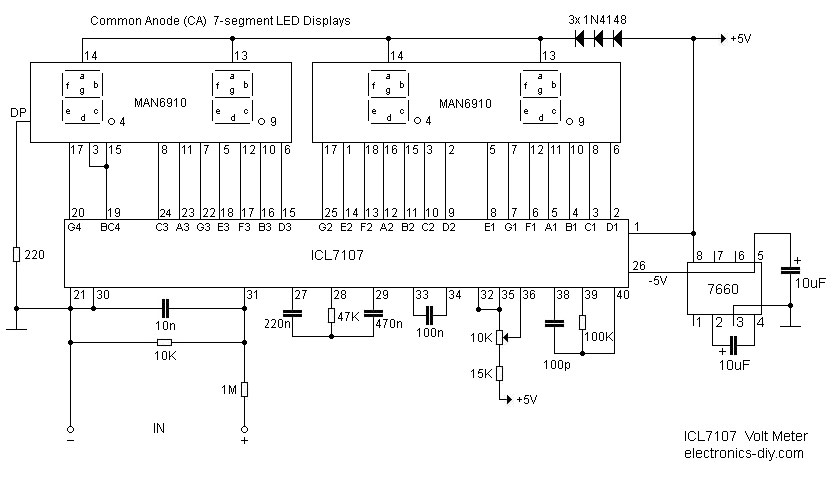
With the Voltage Meter, Everything seems to be ok. when I power it let the in put 0V, I mean, I connect the (+) pin and (-) pin of the INPUT, it displays 00.0 V without fluctuation.

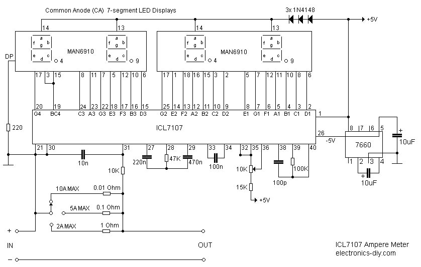
But with the Ampere Meter. I'm facing the problem: When I power it, and connect (+) to (-) to simulate the fact that: no current appears. It floats around 0.6V

I'm wondering why????

When I looked at the PCB, the twos are the same except that, some resistors around TL431 are different.

Can you recommend me some possible reasons relating to ZERO FLOATING phenomena with the IC TCL7107???
 

schematic+7107

To simulate zero current shouldn't you just keep the pins apart?
Zero current means open circuit. By connecting the pins you are short circuiting
them (0V) not 0A!

Also, do you have to change one of the probe on the meter to connect to a "A" (ampere) input? I know some meters have three inputs and you only use two depending on if you are measuring V, A or ohms.

Best regards,
v_c
 

voltage meter problems

Often the problem is caused by the manufacturer's layout. They don't pay attention to the ground layout causing input offsets, from operating current (to drive the circuitry) flowing in some parts of the ground connected between the negative sensing input and gnd reference. You only need 1mV voltage drop for a 1A error.

I have cut and rewired ground points on digital panel meter modules many times to eliminate these random display errors.
 

digital panel meter fluctuation problem

@V_C: well, infact, it mesures the voltage drop on a shunt (if 10A goes through this shunt resistor, the voltage drop is 75mV). So if no current flows through this shunt resistor, the voltage drop is 0V. That makes the meter display 0.00

But in fact, it displays 0.60 and fluctuates around this value.

To simulate 0V, I connect the input (+) to input (-), I think that it should display 0.00 but no.

Thank you E_Design, I'll try your recommendation.
 

pcb for 7107 panel meter

I did as what you recommended me but nothing changes.

I really don't know why????
Can anybody help me????
 

digital display problem

Are the ICL7107s in both PCBs mounted in IC sockets, so would it be possible to swap them over? Just to check if you don't have problem with one of them ..

Also, could you confirm the value of the shunt resistor: 7.5mΩ ? .. sounds a little bit strange ..

Regards,
IanP
 

voltmeter problems

I found 2 meter using ICL 7107, I also found that in my schematics (I destroyed one :cry:), pin 30 and pin 32 and pin 35 is connected together. But in these 2 schematics, pin 32 and 30 is not connected

ICL7107_ampere_meter.jpg


ICL7107_volt_meter.jpg


Is this possible?

Added after 53 minutes:

By the way, can you tell me the role of the resistor R=10K between Pin 31 and Pin (30 or 21)???

Thank you in advance!
 

problem about voltmeter

Hi, no one can help me????
I really need your help. I have tried to find out the problem but now, I'm not successful. Can you recommend me some possible solutions?
 

schematics voltmeter

Hi,
It's perfectly fine to not connect pins 32 and 30. When one does not connect IN LO with Analog Common, there exists a common mode voltage which would be rejected by the CMRR of the device. (See datasheet).

And the resistance 10k is required to discharge the input capacitor when the probes are open. Since the bias currents are of the order of nA, we require an additional discharge path. Otherwise, even when the probes are open, there would be a floating value on the display.

Giri
 

i got a problem, when i finally finished everything nothing worked i saw that my solder was just touching the neg power to pos power so i de-solder the IC to check if it works but on a 1.5 volt battey i'm getting .8 to 4 to 8 then back to 2, is the chip fried?
 

Status
Not open for further replies.

Similar threads

Part and Inventory Search

Welcome to EDABoard.com

Sponsor

Back
Top