Continue to Site

Welcome to EDAboard.com

Welcome to our site! EDAboard.com is an international Electronics Discussion Forum focused on EDA software, circuits, schematics, books, theory, papers, asic, pld, 8051, DSP, Network, RF, Analog Design, PCB, Service Manuals... and a whole lot more! To participate you need to register. Registration is free. Click here to register now.

voltage supply in series with a resistor

Status
Not open for further replies.

preethi19

Full Member level 5
Joined
Jun 30, 2014
Messages
273
Helped
0
Reputation
0
Reaction score
1
Trophy points
16
Activity points
3,474
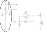
Hi i was learning about RC filter and i came across a circuit. I have attached the image below.
opamp.png
The video wer i found this image is in "Passive RC high pass filter tutorial!" in youtube.
I have circled the part of the circuit wer my doubt is. The 9V supply is used for powering the microphone. So they have arrow marked the node which has a peak to peak signal of 20mV with a DC offset of 9V which comes from the supply. I understand that the supply adds up as an offset with the 20mV signal from the microphone. My doubt is der is a series resistor from the 9V supply. Isnt the voltage supposed to drop down??? I thought a resistor in series connection lets the same current to pass through but causes a voltage drop. Can someone pls clear this for me.. Thank you!!!
 

The diagram is wrong, you are correct.
The microphone draws current which results in a voltage drop in the resistor. The actual voltage will depend on the current drawn by the microphone but typically it would be in the region of 4V, certainly not the 9V shown in the image.

Brian.
 
Another error on the schematic is that the resistor powering the Jfet inside the electret mic should be 10k. The 5k resistor value is too low and cuts the signal level almost in half.

Another error on the schematic is the choice of the opamp. The LM324 is too noisy (hiss) to be a microphone preamp and it is bad for audio because its low supply current causes crossover distortion and a poor slew rate causing loss of high audio frequencies when the output levels are high.

Another error on the schematic is that the opamp is trying to drive a speaker. It cannot provide enough current to drive a speaker.

Another problem on the schematic is that there is a volume control feeding the speaker. But a speaker has a strong resonance that needs damping from the directly connected extremely low output impedance (0.04 ohms or less) of a power amplifier.
 

Resistor in series with a power supply increases the internal impedance of the voltage source and makes it appear more like a current source.

Suppose you want to use 9V to drive a 5V regulator and you need a current of 100mA. The regulator will dissipate all the excess voltage. But if you add a 22E in series on the input side, the resistor too will take up some voltage drop and the regulator will run cooler.

In your example, the voltage drop will be determined by the current taken by the microphone. The signal appears across this resistor because the microphone essentially modulates the current from the supply. The current drawn by the microphone is rather small (uA ranges) and therefore the microphone will see the full supply voltage of 9V.

As pointed out in #3, smaller value of this resistor actually cuts down the signal output level.
 
Hi,

My opinion: it depends.

If the shown microphone is a capacitor microphone, then there will be about no DC current.
Therefore the DC voltage drop across the resistor is about zero.

But with some sound on the microphone it will chanche it's capacitance according the sound.
Charge flows through the capacitor causing AC current.
This current needs a resistor to cause a voltage.

Without the resistor you won't see any AC voltage...nothing to amplify.

Klaus
 

If the shown microphone is a capacitor microphone, then there will be about no DC current.
Therefore the DC voltage drop across the resistor is about zero.
It is an "electret" microphone, look at it in Google. It is a "condenser" microphone that has an extremely high impedance and needs a voltage of about 48V across it PLUS a Jfet to reduce the impedance PLUS some electret material that holds a permanent 48V charge in it. The Jfet in a 2-wires electret mic is common source, uses a current of about 0.5mA and has an output impedance of about 3.3k ohms. Then with a 9V supply for the Jfet to have 4.5V across it then its drain resistor should be 9k ohms but most mics use 10k. The 10k in parallel with the 3.3k drain impedance causes a total output impedance of 2.5k with a fairly low signal voltage gain.
There are also 3-wires electret mics that use the Jfet as a source follower and they are used when the sounds are very loud like inside a piano or drum.

A condenser mic has two plates polarized with 48V and the front plate is perforated to let sounds in. The moving membrane is hung between the plates. The assembly is a capacitor variable voltage divider.
When sound moves the membrane closer to the positive plate then it becomes positive and when the sound moves it away from the positive plate and closer to the negative plate then it becomes less positive or negative. The membrane is not touching anything so it has an extremely high impedance that needs a Jfet (or an old vacuum tube) to be used. An old mic preamp provided the 48V but today electret material is used instead.
 
Status
Not open for further replies.

Part and Inventory Search

Welcome to EDABoard.com

Sponsor

Back
Top