nikens
Junior Member level 2
Hi,
I searched for zener on wikipedia, aslo found some diagram for voltage stabiliser, but don't know where do you apply + and where -.
And if I understand, zener conducts electricity in forward position like regular diode, but its brake down voltage (reverse voltage) is lower and it is determined as zener voltage (like 5, 9, 12V...). So does this mean that reverse biased zener will conducts if input voltage is hgher than zener voltage?
Will that mean that in below diagram zener will conduct if supply will be higher than zener voltage and differences between input voltage and zener voltage, multiply by current flow across zener will be power loss on a zener - zener will produce heat. Is it correct than if I say that + should be brought to the resistor side?
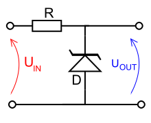 [/img]
I searched for zener on wikipedia, aslo found some diagram for voltage stabiliser, but don't know where do you apply + and where -.
And if I understand, zener conducts electricity in forward position like regular diode, but its brake down voltage (reverse voltage) is lower and it is determined as zener voltage (like 5, 9, 12V...). So does this mean that reverse biased zener will conducts if input voltage is hgher than zener voltage?
Will that mean that in below diagram zener will conduct if supply will be higher than zener voltage and differences between input voltage and zener voltage, multiply by current flow across zener will be power loss on a zener - zener will produce heat. Is it correct than if I say that + should be brought to the resistor side?