Continue to Site

Welcome to EDAboard.com

Welcome to our site! EDAboard.com is an international Electronics Discussion Forum focused on EDA software, circuits, schematics, books, theory, papers, asic, pld, 8051, DSP, Network, RF, Analog Design, PCB, Service Manuals... and a whole lot more! To participate you need to register. Registration is free. Click here to register now.

[SOLVED] Voltage regulator constant current above expected value

Status
Not open for further replies.

d123

Advanced Member level 5
Joined
Jun 7, 2015
Messages
2,505
Helped
494
Reputation
992
Reaction score
525
Trophy points
1,393
Location
Spain
Activity points
27,148
Hi!

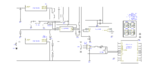
The circuit below is not functioning as I'd hoped/expected. This is an experiment making a milli ohmeter, that is the purpose of this circuit; I was unable to breadboard it, or simulate a couple of the ICs, so I just made a prototype to see what would happen, therefore it's very rough and ready.

Are there any obvious mistakes in the design that would cause a predicted 100mA constant current appear to be in fact 2A?

The voltage regulators are supposed to be putting out 5V and 100mA...
- The 73801 which supplies the ICs does output 5.02V, not sure of its current output (yet) as that is not an issue.
- The 73801 which feeds the DUT resistor part of the circuit supplies a poor 1V, and according to the multimeter is blasting out 2.1A down to 1.6A by the time the 555 "Start" pulse ends. Bad for the battery too. I understand this high current is why the output voltage is only 1V, and not 5.02V.
(The 555 "Start button" sends a signal to the 73801 "enable" pin, otherwise the 73801 for the DUT resistor has 0V output).

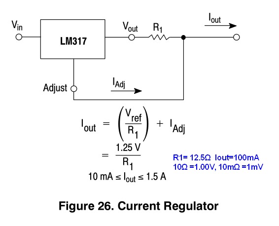
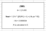
The formula from the TPS73801 datasheet is also here as a jpg. I understood that 1.21V/12.1Ω = 100mA. As the predicted output voltage for the regulator was 5.04V and one is supplying 5.02V, I imagine I have understood that calculation correctly, but don't understand why the current is so high. I used 12.1Ω for R1 and 38Ω for R2.

Any ideas? Is some component like an additional resistor to limit the current missing from this circuit?

Thanks.
 

Attachments

  • Milli Ohmmeter.png
    Milli Ohmmeter.png
    31.6 KB · Views: 126
  • 73801 V and I calculation.JPG
    73801 V and I calculation.JPG
    18.7 KB · Views: 129

You have chosen an adjustable LDO as a voltage source with no current sense resistor, so that will not work.
The concept in LDO's is to regulate the feedback to match the internal Vref. For CC operation this would have to be 1.21 across a current shunt , which dissipates too much power.

Standard Current shunts go for 75mV max drop but this requires amplification..

Change the CC design to a chip more suitable. Some are high side Current shunt sensors, others are low side like this one.
https://www.digikey.com/product-detail/en/LM334MX/NOPB/LM334MX/NOPBCT-ND/4988724
 
  • Like
Reactions: d123

    d123

    Points: 2
    Helpful Answer Positive Rating
Thanks.

So would it be a good starting point to replace the LDO with a device like the one you mention (and placed the link to), and I imagine replacing the current shunt monitor (the 286) with an opamp for an appropriate gain level?
Also, can I omit the current shunt monitor anyway, as I've seen other milli ohmeter circuits where the DUT resistor was placed directly across the ADC In hi and In lo inputs?
 

A CC source will produce a voltage proportional to resistance.
DMM's use about 1 to 2 mA for 0.1 Ohm resolution.
Higher Current sources are used for microOhm resolutions.
LCR meters use CC with a sinewave to measure ESR at 2 frequencies.

Depending on your expectations or specs, you may want to reconsider the entire design.
 
  • Like
Reactions: d123

    d123

    Points: 2
    Helpful Answer Positive Rating
Depending on your expectations or specs, you may want to reconsider the entire design.


Oh dear, it's that bad a design is it?! Oh well, not to worry. You're very polite.

The intention of this excellent circuit was to copy an ammeter circuit but replace the sense resistor on the current shunt monitor with a constant current source. I based the idea on that of "A constant current source will produce a voltage proportional to resistance."
I'd hoped to read from 0 - 999mΩ. I wanted a CC of 100mA, and max. 4V drop across the DUT resistors as it seemed to be a suitable value for 1 Ohm and under from what I'd been reading about these devices, and with the 286 and ADC I'm using.

Any suggestions as to where to start from, if it's better to start the idea from scratch? I think I'd like to tweak the circuit I have by replacing the LDO with a suitable constant current source (so I'll look for appropriate devices), unless I can add a resistor to limit its output current.
I'm only making it "for fun" and to learn a bit more, and get used to well-behaved SOIC and slippery SMD capacitors who don't want to be soldered but slide over molten solder or flip up vertically like tower blocks about fifty times until I get it right.

- But, what interests me is that the 73801 datasheet does say that you can use the device as a kelvin connection "During fixed voltage operation, the FB pin can be used for a Kelvin connection if routed separately to the load.", ...and now that I've looked at the relevant section and schematic in the datasheet (7.3.2) again I see that I have wired it wrong in order to do that, and misinterpreted what it probably actually means.

In your opinion is it better to move onto PIC type devices for this kind of circuit?
 

It depends why you want to use a uC.

TO measure Rs , all you need is an analog meter and a CC source to measure resistance.

The choice of current is limit by the full scale on your voltage reading with/without gain.

With 0.1V full scale and 10 bit conversion with 0.1mV resolution and 1 Ohm limit then 100mA will work with 0.1mOhm resolution.
Add gain to match ADC full scale or simply use 10mA and more gain and low offset OA's.
 
  • Like
Reactions: d123

    d123

    Points: 2
    Helpful Answer Positive Rating
To make my current sensing circuit, I amplified the voltage across a length of wire. It can be adapted for sensing milli-ohms.

 
  • Like
Reactions: d123

    d123

    Points: 2
    Helpful Answer Positive Rating
Hi! Thanks, that's nice, looks workable with my skills.

Sorry, ignorant questions...:

What's the Zener for?

How does that circuit work? I think I'd like to give it a go, and part of the fun is understanding what is happening on-circuit.


What model opamp or type did you use for this, please?
 

Hi! Thanks, that's nice, looks workable with my skills.

Sorry, ignorant questions...:

What's the Zener for?

How does that circuit work? I think I'd like to give it a go, and part of the fun is understanding what is happening on-circuit.

The left-hand section sends a constant current through the unknown resistance (DUT). A voltage develops on the DUT.

The op amp detects and amplifies it in linear relationship to the DUT.

The zener value should be less than supply voltage minus 0.6.

What model opamp or type did you use for this, please?

I should have used a single op amp which has a zero offset adjust. Such an adjustment makes it easy to get zero output when you have zero input. (Example, 741 or better.)

Instead my meter had a 324 quad op amp. (I used a multi-unit because I needed more than one op amp.) However I made problems for myself. I had to go to a lot of work to contrive a resistor network that would create a slightly positive voltage at the input of the 324. Only then did I get zero output with zero input.
 
  • Like
Reactions: d123

    d123

    Points: 2
    Helpful Answer Positive Rating
Hi, that's great, thanks for the explanation, and the additional info.

- Wow, you openly admit to using the 741/324 in a public space ;) Jokes aside, that's a good idea, it may be ancient and not great/popular but it does have offset null pins, and I have a couple; the current shunt monitor (I like a lot) which I used for the ammeter had a little offset (probably due to unavoidable solder points, sil headers, and leads from shunt resistor to the 286, besides the datasheet minimum offset input voltage it says there may be) which is irritating as I have been unable to get rid of it - there will always be a phantom 4 - 5mA on the display in my case.

Thanks for the idea and for sharing the schematic, much appreciated, other discrete constant current sources I'd looked at on the web and read about all used a lot or a few more components, and were a bit offputting thinking about the K.I.S.S. concept.
I think I can fit yours into the spot where the incorrectly chosen LDO and the 286 are on board attempt #1 without having to alter the rest of the circuit, so once again thanks.
 

Sorry to ask, I have a little doubt about something I think I understand but am not 100% sure:

With a constant current source working (hooray!), it's 100mA and 5VDC, the ADC (on +5 and -5VDC supplies) couldn't display/measure resistors over 0.5Ω.

Since powering the ADC on +9 and -9VDC, and the CCS is still 5V/100mA it does show the full range of measured resistors (from 0.005Ω to 1.9Ω).

I was reading an application note about Common Mode Range and the datasheets I have for simple ADCs to try to see why this problem was occurring, and one conclusion I can come to is that the ADC didn't have enough Common Mode Range to work with.

Just guessing from the info. I've provided, does anyone think that was that probably the cause of the problem? Thanks.
 

Hi,

show us your actual schematic and we can help you more.

Klaus
 

Hi Klaus. ...it took a short while to update the original schematic to the version I had on the breadboard yesterday. The pdf is the version that didn't work beyond 447mΩ (4.49V) until I increased the ADC supply voltage to +9 and -9V.

Whilst copying/drawing it just now I think I saw the "Common Mode Range" issue - and my apologies for wasting your time with the Common Mode question: it was a wiring mistake - the CCS resistor was on +9V while the 7106 was on +5 and -5V...

View attachment MilliOhmeter V3 breadboard - Schematic.pdf

Sorry about that, I originally had the breadboard power supply on +5V, then put it on +9V to be able to simulate/see the CCS working with (as best as I can with TO-220/PDIP 7805, 7660 and the 7106) the SOT-223 voltage regulator and SOIC devices for the pcb battery-powered version, and forgot to move the CCS resistor that goes to +V over to the +5V line.
I focussed on the ADC instead of checking the whole breadboard for anomalies/mistakes... 0 points for me.

If it were anything else that caused the problem, please let me know, if not then thanks all the same.

If it's not too cheeky to ask, without having to your waste time looking, do you remember/know if/think the ICL7136 can work off +9 and -9V, as the datasheet wording about supply voltages left me unsure.

Regards,
Daniel
 

Hi,
beyond 447mΩ (4.49V) until I

447mΩ x 100mA = 44.7mV, not 4.49V.

Klaus

- - - Updated - - -

Hi,

with this design you will not get very precise results.
What precision do you expect?

The LED current supplied by the 9V. Is the 9V more stable than the regulated 5V? --> if the 5V is more stable, then use the 5V.

The tempco of the bjt is about -2mv/ °C. What is the tempco of the LED?

The emitter resistors will be about 1.2V, so let 300mV for regulation, then the max usable voltage is 5V - 1.2V - 0.3V = 3.5V. It means 35 Ohms.

Klaus
 
  • Like
Reactions: d123

    d123

    Points: 2
    Helpful Answer Positive Rating
Hi, much later... I was drawing the tracks and "pads" on a copper-clad board most of the afternoon, and before that checking if that circuit works with everything including the CCS resistor on +5V, but it doesn't because the ADC shows no reading, I imagine the input voltage is too low like that so I'll leave it as it is (functioning).

"447mΩ x 100mA = 44.7mV, not 4.49V." ...very correct, I originally tried to use a 100V/V current shunt monitor to boost the input voltage, but as it adds input noise I took it off before encountering the issue that was my question, I forgot - my apologies again, I am forgetful at present with moving house soon and my big goldfish had an operation two days ago (seriously). The circuit pdf is the right wrong one though, at least that's right.

"with this design you will not get very precise results. What precision do you expect?" - Hard to define, just precise enough to not be a waste of my time and of components. It seems reasonably accurate so far: The CC is 99 - 100mA, and after a long time on (about 50 seconds to a minute) rises to 101mA, but seems to stay at 100mA.
Today, for example, The 5% 1Ω 5W reads as 0.950; the 5% 0.5Ω 3.75W reads as 0.478; and the 0R02 metal shunt resistor is a very constant 0.020Ω, even if on for over a minute. I have seen that the resistors which are under 5W creep up in value "quickly", I imagine that's the heat. Yesterday the 0.005Ω metal shunt read as 0.007Ω - 0.008Ω, and a 0.07Ω as something like 0.064Ω, a 0.08Ω as 0.072Ω, and a 5% 2.2Ω 7W as 1.996Ω. - With my ability that is more than enough accuracy...

This will only be on for 10 - 20 seconds at most, enough to get a reading. The BJT will use the cheapo FR1 38uM copper board as a heat-sink.
The LED: sorry, I checked the datasheet and saw no reference to tempco, it's a low power 3mm green through-hole LED.

On the breadboard the 9V is a very stable power supply (like a phone charger plug type), but it will be a battery for the finished circuit - things haven't worked out too well there: I'll use two 9V batteries in parallel so it lasts more than ten resistors... The 5V is a 7805 on the breadboard, but will be a TPS73801 on the circuit, and the last one I used supplied a very stable 5.02V from a battery (the other 73801 I mistakenly tried to use for the CC on the first prototype had an output of not 5.02V and 100mA but 1V and 2A!!!!! Oops.)

I'm sorry, I don't understand the part about: "...It means 35 Ohms."


...And just to finish the day well with another mistake - just take a look at the crocodile clip covers I ordered to go with the fantastic copper clips, they looked smaller in the photo:

Crocodile clips.JPG

Regards
 

Hi, thinking about these two aspects:

The tempco of the bjt is about -2mv/ °C. What is the tempco of the LED?

The emitter resistors will be about 1.2V, so let 300mV for regulation, then the max usable voltage is 5V - 1.2V - 0.3V = 3.5V. It means 35 Ohms.

I copied this CCS:

https://en.wikipedia.org/wiki/Current_source#LED_current_source

because it says "...and also has the additional advantage of tracking (compensating) VBE changes due to temperature.", but if I'm honest, mainly because it was the first CCS I got to work correctly with the components I have here at home.

And for your second point, I'm not sure but I think we may be working off different calculations, which would explain the diffference in emitter resistor value. I used the formula on the Wiki page, and the jpg shows the results for a rough calculation, which does coincide a lot with the values I'm using of (5% resistors) 1K + 200R, and 10R + 2R2 for the emitter resistor.

Hope these points answer a couple of your questions better, and many thanks.

Regards,

Daniel
 

Attachments

  • CCS calculations.JPG
    CCS calculations.JPG
    73.4 KB · Views: 101

Why would a mains-powered and a battery-powered device have different output voltage readings, depending on which power source is used? I've been looking for info. but am unsure about the search term to use to find what I want to understand.

The milliohmeter, when powered by a mains adapter on 9VDC reads 1Ω as 105mV (1.050Ω), but when powered by a 9V battery with 8.66V available reads 115mV (1.150Ω) and looks like it would continue to rise if left on. Also, a 0.02Ω reads as a steady 2mV using the adapter supply, but oscillates from 0.020Ω to 0.021Ω on the display when powered by the battery.

I've looked for things related to battery impedance, but not sure if that's the right area to look at.

Thanks for any explanations.
 

The milliohmeter, when powered by a mains adapter on 9VDC reads 1Ω as 105mV (1.050Ω), but when powered by a 9V battery with 8.66V available reads 115mV (1.150Ω)

Perhaps normally there would be internal voltage regulation, because you want precise repeatable measurements under all range of supply voltage.

However in your milliohmeter, it may be more effective to apply raw supply V, because a voltage regulator might require certain conditions to operate, or it might create nonlinear response, etc.
 
  • Like
Reactions: d123

    d123

    Points: 2
    Helpful Answer Positive Rating
Since LDO's like the adjustable LM317 are so cheap ($0.57 @ 1pc) in TO-220 cases and include a precision 2.50V bandgap reference, which is far superior to a Zener, I suggest you get this with a 12.5Ω 1/4W resistor. Or make from several R and tune to 0.5% with a calibrated resistor using DMM.

It doesn't get any simpler than this.
Caps can be added to reduce noise as recommended.

Total cost ~$1
8929171500_1441046897.jpg
 
  • Like
Reactions: d123

    d123

    Points: 2
    Helpful Answer Positive Rating
Status
Not open for further replies.

Part and Inventory Search

Welcome to EDABoard.com

Sponsor

Back
Top