Continue to Site

Welcome to EDAboard.com

Welcome to our site! EDAboard.com is an international Electronics Discussion Forum focused on EDA software, circuits, schematics, books, theory, papers, asic, pld, 8051, DSP, Network, RF, Analog Design, PCB, Service Manuals... and a whole lot more! To participate you need to register. Registration is free. Click here to register now.

Voltage measurement

Status
Not open for further replies.

Rajinder1268

Full Member level 3
Joined
Mar 20, 2021
Messages
162
Helped
1
Reputation
2
Reaction score
4
Trophy points
18
Activity points
1,228
Hi,
I have a requirement to measure voltages from a 10 pin header. I am interested in measuring 5V, 3V3 and 1V8 supplies with an accuracy of +/- 10mV. It is part of an automated test equipment, so really can't use a DVM.
If all the voltages are within range then indicate using a LED.
Not sure how to approach this.
Any help would be appreciated.
 

Hi,

Where exactly is the problem? Ask a clear, elaborated question.

I mean some DVMs have a digital interface.

But you may also use ADC modules, maybe connected via USB.


Or you may use a microcontroller with built in or external ADC.
Basically what you need:
* ADC with accurate voltage reference
* maybe accurate enough voltage dividers
* I recommend a capacitor as LPF
* microcontroller with a little piece of software

Klaus
 
Hi,

use a MCU and an ADC which supports a reference voltage / full-scale-range larger than 5 V, e.g. 6 V. Select an ADC with sufficient resolution, here a 12 Bit ADC in combination with a 6 V FSR should provide ~1.5 mV resolution, check the effective number of Bits of the ADC. Here, an ENOB of 10 Bit should be sufficient BUT this is only your resolution.

To give a feedback on the accuracy we need more information about the voltages which should be masured e.g. are this supply voltages or sensor signals. Temperature might be also of interest. Depending on this information a signal conditioning might be required e.g. a buffering structure which effects the accuracy. E.g. introducing an offset, which might be compensated by an offset (gain) calibration.

BR
 

Hi,
I was thinking of a microcontroller/ ADC option. The 3V3 is used to power an LCD and also other peripherals. The 5V is for CAN Comms, 1V8 is microcontroller core.

What would be the input circuit conditioning for the ADC? Just an LPF? Also how can I determine the values of RC.
 

Without any further knowledge, a resitor divider will do the job, as mentioned by @KlausST

For the LPF the ADC sampling frequency has to be considered (fc < fs/2), as well as the frequencies expected to be observed or supressed within your observed voltages.
 

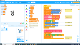
Using simple block language, mBlock, and an ATTINY85 8 pin dip micro :

1680704366372.jpeg


1680704569129.png


You need R divider on 5V input. You can ad averaging to get noise suppression on rail.

To program the ATTINY85 you do it with a Arduino UNO or Nano board, used as in circuit
programmer.

mBlock converts your block code to Arduino, and you use the Arduino IDE
to program the part.


Regards, Dana.
--- Updated ---

Alternatively use a PSOC, which is a single chip SOC, routable :

1680704755386.png


Shown above basic A/D or use one of the 3 power supervision components (a component in
PSOC is an internal resource).

Also there are DACs so you can do trim if needed on external supplies.

Here is what is on a PSOC, multiple copies of these components in many cases :

1680704940006.png


Each component has a rich set of libraries, basically f() calls, to manipulate the component.

Note onboard Vref is good to +/- .1%

IDE, PSOC Creator, and Compiler free. Good board for this would be $15, CY8CKIT-059.


Regards, Dana.
 

Attachments

  • 1680704271124.png
    1680704271124.png
    241.3 KB · Views: 77
Last edited:

Note in post #8 you could also pulse led according to which supply
is posting a problem, just a thought. Or put out a message on a low
cost display. In PSOC case even do a PC alert over USBUART......

Either solution could do led approach.


Regards, Dana.
 

how can I determine the values of RC.
It largely depends upon how fast you need to take each reading.
Typically you want as large an RC value as possible to suppress any noise but, to settle within 1mV of 5V (worst-case voltage), requires about 7 time-constants, so that would be the maximum.
 
It largely depends upon how fast you need to take each reading.
Typically you want as large an RC value as possible to suppress any noise but, to settle within 1mV of 5V (worst-case voltage), requires about 7 time-constants, so that would be the maximum.
Would I need to have a unity gain buffer before my RC filter?
 

Status
Not open for further replies.

Similar threads

Part and Inventory Search

Welcome to EDABoard.com

Sponsor

Back
Top