Continue to Site

Welcome to EDAboard.com

Welcome to our site! EDAboard.com is an international Electronics Discussion Forum focused on EDA software, circuits, schematics, books, theory, papers, asic, pld, 8051, DSP, Network, RF, Analog Design, PCB, Service Manuals... and a whole lot more! To participate you need to register. Registration is free. Click here to register now.

Voltage follower with resistance input divider

Status
Not open for further replies.

patlas

Newbie level 5
Joined
Nov 9, 2010
Messages
9
Helped
0
Reputation
0
Reaction score
0
Trophy points
1,281
Activity points
1,334
Hi,

Recently I had to add voltage follower to my current probe (Tektronix P6022). I use fast enough opamp in my construction (LT1819). Everything works if I connect directly current probe to input of apamp but I need to scale input voltage by 2 so I try to insert resistance divider (1M/1M).
After that my voltage follower stop working propertly. Working frequency is 7MHz and without divider it works fine but when I include divider it works only at about 1kHz.

What am I doing wrong?

schematic.png
 

Try placing the PD on the output of the OP-amp. Reduce the value of the resistors to account for the input capacitance of the device your connecting to.
Thanks
Adam
 

Did you calculate the low-pass formed by the voltage divider and OP input capacitance? It's about 200 kHz, probably lower due to additional circuit capacitance. You also get some signal attenuation by the OP input resistance and excessive noise generated by the OP noise current in combination with the divider resistance. Welcome to the fascinating world of wideband analog circuits.

Now calculate reasonable resistance values. I would start with 1k as a first guess.
 
  • Like
Reactions: patlas

    patlas

    Points: 2
    Helpful Answer Positive Rating
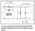
A x10 'scope probe has a trimmer capacitor parallel with the input resistor to make a high frequency voltage divider so that the high frequencies are not attenuated too much by the input capacitance of the 'scope (the opamp and its input wiring) in your circuit).
 

Attachments

  • scope probe.png
    scope probe.png
    25.8 KB · Views: 99
  • Like
Reactions: patlas

    patlas

    Points: 2
    Helpful Answer Positive Rating
Thanks for all replay, all of them are really helpful for me :)
FvM Could you tell me how did you calculate my cut off frequency about 200kHz? Could you recommend me some literature connected with wideband circuits, or rather RF circuits?
 

I don't understand parallel connection of 1Meg resistance. Firm resistor comes form divider but second?
schematic.png
R = R2 || "??"
 

fcutoff = 1/(2pi*R*C), R = 1Meg || 1Meg = 500 k, C = 1.5 pF (OP Cin)

- - - Updated - - -

Source resistance is assumed << 1 Meg, so R = R1 || R2
 
  • Like
Reactions: patlas

    patlas

    Points: 2
    Helpful Answer Positive Rating
Status
Not open for further replies.

Similar threads

Part and Inventory Search

Welcome to EDABoard.com

Sponsor

Back
Top