amirtaha2541
Junior Member level 1
what whenever i attach a load to my inverter the dc bus voltage drops and in load=400watt input mosfets burns?
inverter is modified sinewave
inverter is modified sinewave
Follow along with the video below to see how to install our site as a web app on your home screen.
Note: This feature may not be available in some browsers.
The high current that flows as a load is attached may cause the dc bus voltage to drop, depending on the battery, input capacitance, etc.
The MOSFET burning is another thing. The inrush may damage it, but MOSFETs usually have a high surge current capacity. Maybe the MOSFETs aren't capable of taking the amount of current going through, or heatsinking is insufficient and the MOSFETs overheat and burn.
Hope this helps.
Tahmid.
---------- Post added at 18:18 ---------- Previous post was at 18:16 ----------
There could also be other reasons. Is this the first time the MOSFETs burnt? Did you use this inverter successfully at a lower power level? Is it the first time you're using this inverter?
In this case, I guess, the problem is in the feedback part.
From the figures you posted, you can see that as load is increased, the DC bus voltage drops. This means that the PWM on the primary side is not adjusting pulse width properly for proper feedback.
Do you have an oscilloscope at hand?
Can you show the waveforms at the gate of the MOSFETs at 40W, 145W, etc? This would help identify if the problem is in this section.
Is it an inverter you made? Did you wind the transformer? What are the transformer turns? You may have insufficient secondary turns.
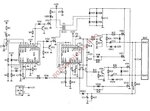
Is there any feedback there at all? Do you have a schematic? Can you identify the PWM controller? Is it SG3525, SG3524, TL494, LM5030 or some other controller?
---------- Post added at 01:55 ---------- Previous post was at 01:55 ----------
It is possible that some part in the feedback section is damaged and thus feedback isn't working properly.
without posting the full circuit diagram, we can only make intelligent guesses
as to what can be the problem and solution