Continue to Site

Welcome to EDAboard.com

Welcome to our site! EDAboard.com is an international Electronics Discussion Forum focused on EDA software, circuits, schematics, books, theory, papers, asic, pld, 8051, DSP, Network, RF, Analog Design, PCB, Service Manuals... and a whole lot more! To participate you need to register. Registration is free. Click here to register now.

Voltage Divider Circuit for a Range

Status
Not open for further replies.

tiwari.sachin

Full Member level 6
Joined
Aug 1, 2009
Messages
341
Helped
3
Reputation
6
Reaction score
3
Trophy points
1,298
Location
India
Activity points
4,449
I need to design a circuit with the following details

when input is 8.5V, Ouput should be 3V
when input decreases to say 5.5V, Ouput should be close to 0V


basically input will vary from 5.5 to 8.5
and output should vary from close to 0 to about 3V

I am not sure how to use a voltage divider as the resistance shall be fixed values

The input voltage and required output voltage looks something as given below

graph.png
 
Last edited:

the application is not specified in your post.

on choice is:connect a voltage source of 5.5v in reverse polarity , in series with your input.

the o/p will have a 0 to 3v range.
 

The input voltage is from a analog source that varies from 5.5 to about 8.6V (Approx)

I cannot change the polarity of the source
 

Hi,

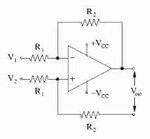
Mathematically it means: Gain =1, just subtract 5.5V.

A simple differential amplifier circuit should do. 4 equal resistors.
diffOpamp.jpg

One 5.5V voltage reference or one -5.5V reference, whatever is easier for you. (it can be made with two simple resistors in simples case)

Klaus
 

I have only one supply (3.3V). The range 6.5 to 8.5 is basically a battery output that needs to be monitored.

- - - Updated - - -

I am only only interested in 6.5 to 8.5V and I want that to be full scale 0 to 3.3V or 3V

I have a single supply that can provide 3.3V, from the battery
 

Hi,

battery voltage monitoring....

I don´t think you need a 1mV accuracy nor a 1mV resolution.

--> use a simple voltage divider and be happy with a 3mV resolution.

Klaus
 

I tried that. The voltage varies from 1.85 to about 2.1

I was thinking if I could increase this range.

There are some moments where are voltage drops (Due to the load) and then the battery reading goes wrong.
 

Drop a few volts by means of a series zener diode (led's, diodes). Take the output and then divide it down. This is the principle of an expanded scale meter.
 

Hi,

There are some moments where are voltage drops (Due to the load) and then the battery reading goes wrong.
I don´t undertand. It is quite normal, that a loaded battery shows less voltage than unloaded.
So if your measurement shows less voltage, then that´s the truth and the reading is correct.

Klaus
 

Hi,


I don´t undertand. It is quite normal, that a loaded battery shows less voltage than unloaded.
So if your measurement shows less voltage, then that´s the truth and the reading is correct.

Klaus


What the software team is doing is continuously checking battery voltage and depending of that the printing intensity is controlled.

For example, if the battery is at 8.4V (read as 100%), the print intensity say is max. but while printing if the voltage drops and on next read it is taken as 75% (because of the drop in voltage) and print intensity is reduced (in software)

I know that there will be drop in voltage as the load will be more when printing. They tell me to make sure that the voltage stays constant even when printing and unfortunately I am not given budget to have a higher capacity battery.

So I was wondering if there are any options to either have a larger range so that the ADC read can be controlled (or neglected) when printing or better have constant voltage at printing too
 

Hi,

Please keep your focus on the measurement of the battery voltage. (

The divider won´t change the voltage drop.

Independent what solution you choose, if the voltage drops it will be measured. And this is what it should do.

So the difference is, that one has a resolution of 1mV, the other 3mV.

--> If you need a better resolution than 3mV then you need an active (Opamp circuit) solution.
If you are satisfied with a 3mV resolution, then simply use the resistors.

It doesn´t change anything on software, nor battery or anything else.

Klaus
 

So I was wondering if there are any options to either have a larger range so that the ADC read can be controlled (or neglected) when printing or better have constant voltage at printing too

For CONSTANT voltage you need a voltage regulator. Look at LDO regulators
 

Status
Not open for further replies.

Part and Inventory Search

Welcome to EDABoard.com

Sponsor

Back
Top