siddarth.ghaste
Advanced Member level 4
- Joined
- Feb 5, 2013
- Messages
- 109
- Helped
- 2
- Reputation
- 4
- Reaction score
- 2
- Trophy points
- 1,298
- Location
- Bengaluru,Karnataka,INDIA
- Activity points
- 1,911
HI
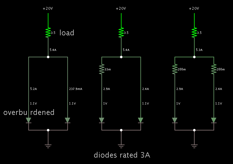
Can anybody tell me how to calculate voltage balancing resistor....
Can anybody tell me how to calculate voltage balancing resistor....