Continue to Site

Welcome to EDAboard.com

Welcome to our site! EDAboard.com is an international Electronics Discussion Forum focused on EDA software, circuits, schematics, books, theory, papers, asic, pld, 8051, DSP, Network, RF, Analog Design, PCB, Service Manuals... and a whole lot more! To participate you need to register. Registration is free. Click here to register now.

Voltage and current profiles on patch antenna

Status
Not open for further replies.

yefj

Advanced Member level 4
Joined
Sep 12, 2019
Messages
1,189
Helped
1
Reputation
2
Reaction score
3
Trophy points
38
Activity points
7,174
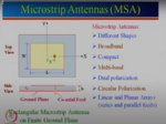
Hello on the antenna bellow we have L=half wave length.
I understand that we have open circuit on the edges so currect is zero on edges
but why its maximal in the middle ,and why voltage acts by going from +vmax on one edge to -Vmax on other edge.
is there some physical explanation for it?
Thanks.

1616702596962.png
 

Attachments

  • 1616702445530.png
    1616702445530.png
    1.1 MB · Views: 74

It might be easier to understand by going back to earlier days...
When the antenna had twin-lead cable attached across a gap at midpoint. The antenna was 1/2 wavelength, yet separated into two halves. I guess it's to provide a node to tap for current (a power source, as it were) in order to drive components in a receiver (impedance matching, preamplifier, detector).

Anyway that describes the VHF tv antenna, in the form of 'rabbit ears' or the driver element of a yagi.

Thinking about the UHF antenna for contrast and comparison...
This often was a circular loop or bowtie, connected to two screw terminals. It's hard to figure out (conceptually speaking) whether the leads are connected at the midpoint or at the ends.
 
  • Like
Reactions: yefj

    yefj

    Points: 2
    Helpful Answer Positive Rating
Status
Not open for further replies.

Part and Inventory Search

Welcome to EDABoard.com

Sponsor

Back
Top