Continue to Site

Welcome to EDAboard.com

Welcome to our site! EDAboard.com is an international Electronics Discussion Forum focused on EDA software, circuits, schematics, books, theory, papers, asic, pld, 8051, DSP, Network, RF, Analog Design, PCB, Service Manuals... and a whole lot more! To participate you need to register. Registration is free. Click here to register now.

visualizing mode attenuation in CST

Status
Not open for further replies.

yefj

Advanced Member level 4
Joined
Sep 12, 2019
Messages
1,180
Helped
1
Reputation
2
Reaction score
3
Trophy points
38
Activity points
7,111
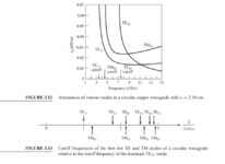
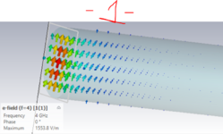
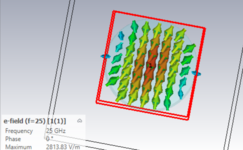
Hello,I have built a circular waveguide as shown bellow,I got a mode photos as shown bellow.
but they look very different from the modes in the photo from pozar book.
please help me with a way to recognize the mode by its shape?


1627498660161.png


1627499631953.png

1627500144067.png


1627502157384.png


1627502418573.png


1627502463195.png
 

Attachments

  • 1627498611617.png
    1627498611617.png
    123.1 KB · Views: 100
  • 1627499909226.png
    1627499909226.png
    180.4 KB · Views: 108
  • 1627502287027.png
    1627502287027.png
    167.7 KB · Views: 102
Last edited:

Could you please say by what intuition you interpreted these modes?
Thanks.
 

Hello i have recognized TE01 mode from the book.
but again i cant see the logic in the plot to say
"aha this a TE01"
1627590937918.png
 

Hello,Could youplease say on the plot where is the azimuth and where is the radial?
Thanks.

1627659071814.png
 

Status
Not open for further replies.

Part and Inventory Search

Welcome to EDABoard.com

Sponsor

Back
Top