Continue to Site

Welcome to EDAboard.com

Welcome to our site! EDAboard.com is an international Electronics Discussion Forum focused on EDA software, circuits, schematics, books, theory, papers, asic, pld, 8051, DSP, Network, RF, Analog Design, PCB, Service Manuals... and a whole lot more! To participate you need to register. Registration is free. Click here to register now.

Visitor counter WITHOUT using Microcontrollers..?

Status
Not open for further replies.

nithin kamath

Junior Member level 1
Joined
Mar 14, 2012
Messages
18
Helped
2
Reputation
4
Reaction score
2
Trophy points
1,283
Location
India
Activity points
1,429
Hi... I need a help from u all... I am doing "A bidirectional Visitor Counter" using a pair of Infrared LEDs and Photo Diodes..... I googled about this, but each and every result uses a microcontroller in it....
I am a Computer Science Student and dont have much Idea about Microcontrollers....

So can i Make a Visitor Counter Without using any Microcontroller...???

I have an Idea,, But before trying that, I thought i can get Much more Ideas from u people who are very much concerned about Electronics.....

Please Help me .... Make it as simpler as possible..... Hope u all can help me...

Thanks in advance :)
 

You would need to implement logic that can understand which photodiode output went low, and in which order, and be able to handle things like a visitor changing their mind half-way and walking back out before the second photodiode output goes low. You may also need to implement circuitry that actually pulses the LEDs, to be able to use the circuit in varying light conditions. Now you can choose to implement that logic in (say) discrete gates (good luck, the circuit will be the size of a PC motherboard), or using programmable logic or a computing device. The choice between the latter two depends on what you're comfortable with.
 

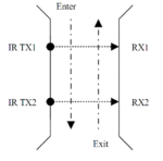
First, you may try this circuit. The detector section consists of two IR LEDs, and two photodiode/phototransistors. The movement of objects including the direction of their movement is detected by the arrangement of the IR LED and photodiode detector pairs. The photodiode of each pair is mounted opposite to its corresponding IR LED fall directly on the photodiode detector.

In practice it’s very important how to position the LEDs and phototransistors in order to obtain the best results.

A more complicated circuit presented on the second picture. Here we use additional comparators to obtain a more sensitive circuit and the possibility to control the trigger level.
 

Attachments

  • photocounter.GIF
    photocounter.GIF
    36.5 KB · Views: 327
  • IR_TX_RX.GIF
    IR_TX_RX.GIF
    10.4 KB · Views: 271
  • photocounter 2a.gif
    photocounter 2a.gif
    45.4 KB · Views: 402
Unless the actual "gate/corridor/passage" and rate of visitors are very constrained it would be difficult to be to build a accurate counter without a micro. Take for instance a bunch of people whose silouettes are overlapping. They would appear to a photo cell, to be one person 12 feet long! :)
Frank
 

Neither using some microcontrollers doesn’t solve this problem, that’s a break-beam sensor general deficiency, and for a more complicated project maybe need to use different types of detectors, as for example pad sensors, body heat sensor (pyro sensor) or a combination of the two sensors.
Accurate counter results depend on the clarity of the events recorded. The aim should be to ensure that there is one well-separated and clearly identifiable count registered by the counter for each person that passes. We need to create gate points where people move freely in single file so long as it can detect only one person at a time and it results in one count per visitor using the gate.

---------- Post added at 01:26 ---------- Previous post was at 01:13 ----------

;-)
One example of dedicated solution that allows for automatic counting of passers using a camera here:
**broken link removed**
 
Unless the actual "gate/corridor/passage" and rate of visitors are very constrained it would be difficult to be to build a accurate counter without a micro. Take for instance a bunch of people whose silouettes are overlapping. They would appear to a photo cell, to be one person 12 feet long! :)
Frank

Hahaha :smile: Actually its correct... But u may have seen, in most of the places where the person counters are installed they make a passage in such a way that only one person can pass through it at a time.... Ya i too agree, nowadays advanced systems are being used which uses different techniques.... but am a newbie in this field... Sooooooooo................ :smile: :smile:

---------- Post added at 19:49 ---------- Previous post was at 19:36 ----------

First, you may try this circuit. The detector section consists of two IR LEDs, and two photodiode/phototransistors. The movement of objects including the direction of their movement is detected by the arrangement of the IR LED and photodiode detector pairs. The photodiode of each pair is mounted opposite to its corresponding IR LED fall directly on the photodiode detector.

In practice it’s very important how to position the LEDs and phototransistors in order to obtain the best results.

A more complicated circuit presented on the second picture. Here we use additional comparators to obtain a more sensitive circuit and the possibility to control the trigger level.

Thank u :) This was very helpfull..... I'll try this... if i need any further assistance i''l post it.... :smile:
 

are you still looking for it..?? b coz i have done the same project.. may be i can help u..

Thanks for your concern.. i had almost forgot i have posted this thread... :lol: Actually i had dropped this project... But as you have done this project, if u provide me the details it'll be helpful for me to start again the project...
Details with a circuit diagram will be so much helpful :)

Thanks again..
 

Look here:


I think that's actually the implementation of the mister_rf diagrams attached few lines above .... :grin:
 

PAGE-1 and 2 shows the receiver Section.
in this section i used IN, OUT and Balance(IN-OUT) in seperate displays. each of them uses 3 digits. ie it will count from 000 to 999. and reset to zero.
 

Attachments

  • Receiver PAGE1.pdf
    30.3 KB · Views: 152
  • Receiver PAGE2.pdf
    18.2 KB · Views: 106

Status
Not open for further replies.

Similar threads

Part and Inventory Search

Welcome to EDABoard.com

Sponsor

Back
Top